Previously (here) I wrote a blog post on how to repair a fraying MacBook power cord and took the easy way out–by simply supporting the fraying section with electrical tape and heat shrink wrap. This method failed in multiple ways because 1. the power brick gets hot and it melted the electrical tape, creating what ended up looking like this:

And 2, a short developed in the negative lead and it stopped charging my MacBook. So, it became apparent that I needed to really fix it this time and I’m down with that. It just involves more work but now’s the time. Here’s how to do it…
How to Repair a Fraying MacBook Power Cord – Take 2
Parts Needed:
- Apple Macbook 85W AC Power Adapter
(if you just want an entire new power cord)
- Zip Ties
Tools Needed:
- Electronic Cleaner
- Bent Nose Needle Nose Pliers
- Safety Glasses
- Soldering Iron (I purchased this model and really like it)
- Solder
- Desoldering Wick
(optional)
- Solder Sucker
- Drill Bit
- Drill
Step 1: Clean off the sticky mess (in my case).
Now I have to backtrack and recover from my first attempt to solve this problem. I purchased some electronics cleaner a while back at Radio Shack and it has worked very well on sticky stuff like this.
 |
| Precision Electronics Cleaner from Radio Shack |
Spray some on your cord and then wipe off with a paper towel. It took me a couple of rounds to get it about as good as I think it will get.
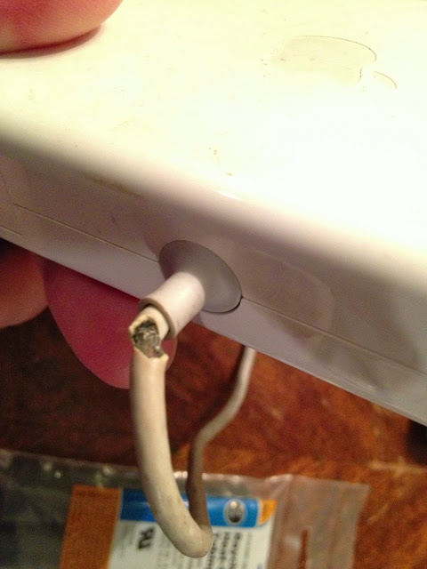
 |
| The now clean but yet fraying MacBook power cord. |
Step 2: Crack open up the power cord case.
It is ultrasonically welded so you just need to pop it open. The easiest way is to use a needle nose pliers in reverse and pry open like shown below. One thing to note is that there are two small plastic pieces that hold springs for the cord wrap “wings” that may come flying out when you do this. Keep your eyes open for them. They are easy to put back in place.
 |
| Prying open a MacBook Power Cord |
Once you have popped open both sides you can take off the case, revealing the electronics:
 |
| Case removed from MacBook Power Brick |
Step 3: Peel back the tape and bend back the grounding shield to show the circuit board.
In the picture below you’ll need to bend back from right to left the metal shielding that wraps around from the left side to see where the wires connect to the circuit board. Don’t worry about bending it, it will bend easily back when you are done.
 |
| With the shielding removed you can see where the power cord connects to the circuit board |
There are two wires–a white positive and a black negative/shielding wire. You’ll want to locate where those two wires connect to the board and then figure out where they poke through to the back of the board so you can desolder them. Also, take note of which one goes where so you can put them back correctly. I was able to desolder them with only using a solder sucker but you could use desoldering tape too if they stick for you. I pretty much just heated up the solder joint and ran the solder sucker on each joint once and then heated them up and pulled at the same time and they came right out. Make sure not to loose the ferrite bead that the wires run through–you’ll want to put this back (it removes any high static frequency from the power). Once I got the wires unsoldered, this is what I was left with:
 |
| The power cord has been freed from the circuit board |
Step 4: Take note of the wire lengths.
For a record of the cord lengths sticking through the grommet I traced the cord as it stuck through the grommet so I could size it correctly. This is what it looked like:
 |
| The wires removed from the rubber grommet with the cord lengths traced in the background for reference. |
Now you can remove the cord from the rubber grommet and trim off the fraying portion of cord. You can pull off the ferrite bead and clean off the glue they used to secure it. Pull out the wires from the rubber grommet. You can see what mine looked like above. One thing to note is that there really aren’t 2 wires, it’s a single center conductor and the ground is the woven shield that surrounds the conductor. You’ll need to separate the shielding and twist it together to make a wire you can push through the grommet.
Step 5: Use heat shrink to shield the ground wire.
You’ll want to use the smallest diameter heat shrink tube you can get away with so it will fit through the hole in the rubber grommet.
 |
| Applying heat shrink tube to the ground wire |
Step 6: Bore out the holes in the rubber grommet.
I couldn’t feed the wires through as it was so I made the holes slightly larger with my drill.
 |
| Drilling out the holes, carefully… |
Step 7: Reinstall the ferrite bead and feed the wires through the rubber grommet.
Be careful not to pull the heat shrink off the ground wire when you are pulling it through (like I did the first time). My iPhone was running out of batteries when I was doing this repair and I didn’t get a picture of it when I fed the wires through the grommet. Length-wise it should look like what I traced on the paper above.
Step 8: Tin the ends of the wires.
This means to simply put some solder on the bare wire ends so they are easier to solder once you put them into the board.
Step 9: Insert the wires into the board and solder them in place.
Make sure you put them in the correct holes!
 |
| The wires have been inserted into the board and are now ready to be re-soldered in place |
Step 10: Clip off any extra wire/solder sticking up from the board.
Space is an issue and you’ll need to lay down the metal shielding back on top of the board so you can’t have a sharp wire sticking up from the board.

Step 11: Bend the shielding back down on top of the circuit board and re-apply the tape.
 |
| Here I’ve bent the shielding back down and taped it in place. |
Step 12: Reassemble the power brick case.
 |
| Using 2 zip ties to make one bigger one |
 |
| Using zip ties to hold the case together, not pretty but effective (and reversible) |
Amazon Associate Disclosure: As an Amazon Associate I earn from qualifying purchases. This means if you click on an affiliate link and purchase the item, I will receive an affiliate commission. The price of the item is the same whether it is an affiliate link or not. Regardless, I only recommend products or services I believe will add value to Share Your Repair readers. By using the affiliate links, you are helping support Share Your Repair, and I genuinely appreciate your support.