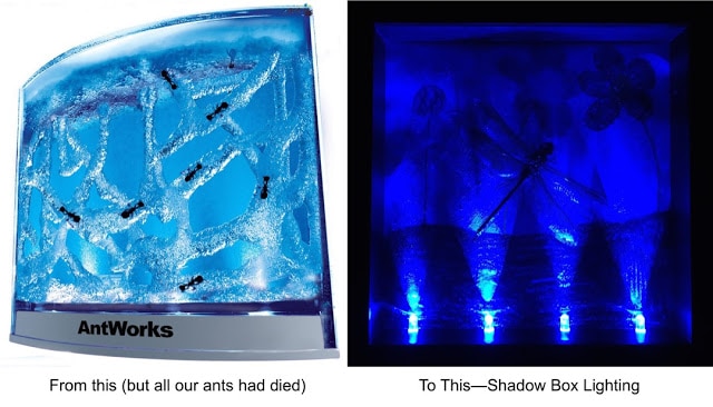
I was on my back porch one evening and I saw a sparrow behaving oddly in the grass, flying up and down, pouncing on something, and went down to investigate. What I found was a large injured dragonfly. At our house we love all kinds of bugs and animals so I scooped up the dragonfly and put it in my daughters bug cage. My daughter tried to nurse the dragonfly back to health but it ended up dying and I decided we should pin it and make some artwork. I had an extra shadow box so I decided to display the dragonfly in there. After cleaning out my workshop and running across the LED base for the AntWorks ant farm that I’d kept after all the ants died and I wanted to merge the two:
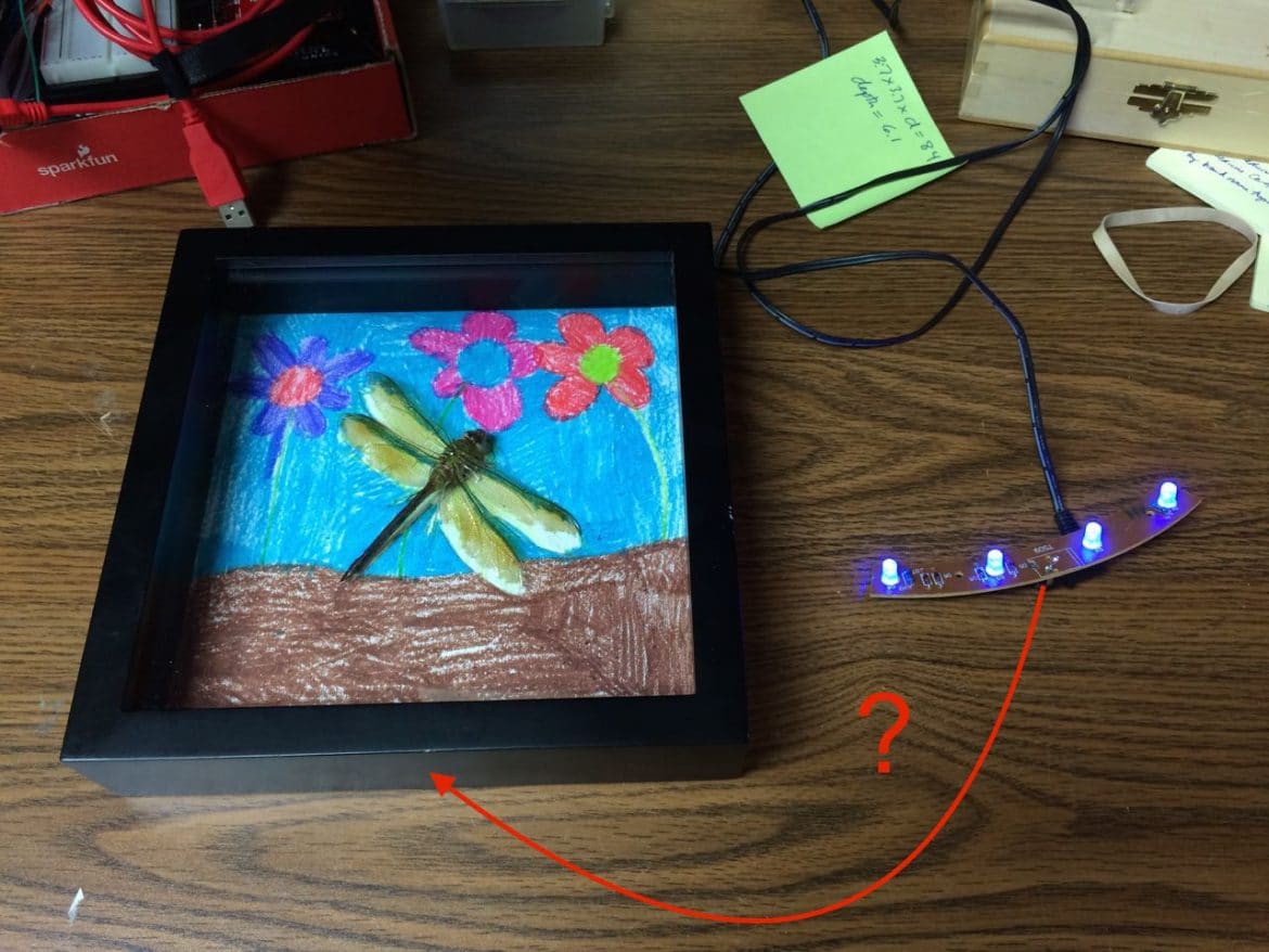
The AntWorks LED circuit board is curved and my shadow box is flat so I first I considered cutting the circuit board to make it straight but then I’d need to connect up the traces that would be cut by cutting the circuit board. Then I had an idea as to how I could make it work and reuse LEDs from Antworks Ant Farm in my daughter’s shadow box and here’s how…
How to Reuse LEDs From Antworks Ant Farm
Hardware:
Tools Needed:
- Safety Glasses
- Phillips-head screwdriver
- Dremel Tool
- Dremel Drill Bit Set
- Dremel Router Bit
- Dremel 4486 MultiPro Keyless Chuck
- Soldering Iron (I purchased this model and really like it)
- Solder Sucker
- Extra Set of Hands Tool
- Wire Stripper
- Flush Cutter Wire Nipper
- Hot Glue Gun
- 6-Inch Steel Spring Clamp (to hold your extra set of hands in place)
Parts Needed:
- Fine Insulated Wire (I recycled old Cat-5 pairs for this project but you could use any fine wire you have around, telephone wire for example). If I built this again I’d probably use some magnet wire
I recently purchased–it is super fine and easy to hide, just make sure you scrape off the enamel from the ends before you try to solder it) - Solder
(make sure you get the kind with flux core)
- High Temp Glue Sticks
- Dragonfly or any other large insect for pinning or folded paper artwork maybe (you’re on your own there)
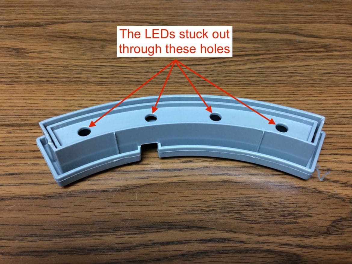
Step 1: Remove the LED circuit from the base.
I didn’t take a picture of this part but this is what the base looks like when it is assembled, and the LEDs stuck out those holes:
To open up the case pry along the edge and the cover will pop off:
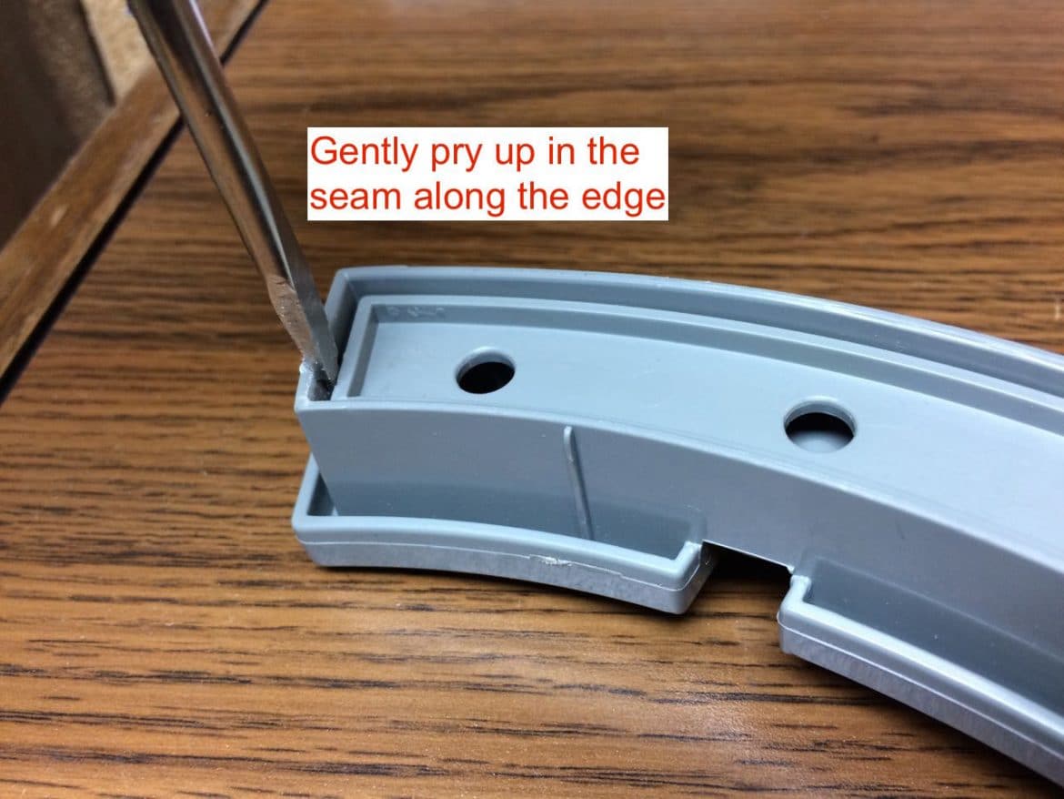
Once you have popped off the cover there were 2 phillips-headed screws that you need to remove to free the circuit board.
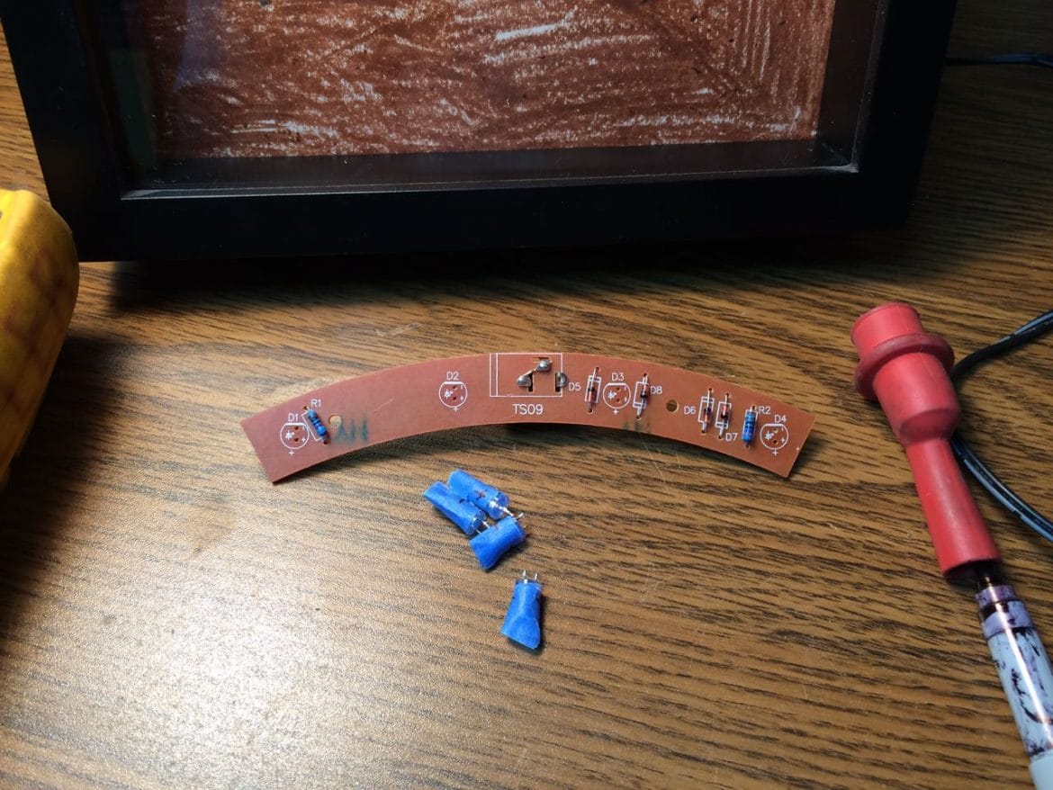
Step 2: Unsolder the LED’s.
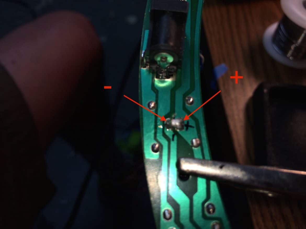
Although you can tell the polarity of the LEDs by looking closely at the internals of them, I didn’t want there to be any question. Typically when you are working with new (thru-hole) LEDs you know that the long leg of the LED is the positive or Anode and the short leg is the negative or Cathode but the legs of these LEDs had been cut off flush on the circuit board. I simply put a piece of masking tape on the LEDs and labeled them according to the positive (+) and negative (-) markings on the circuit board. Then I heated up both solder joints simultaneously and removed all four LEDs:
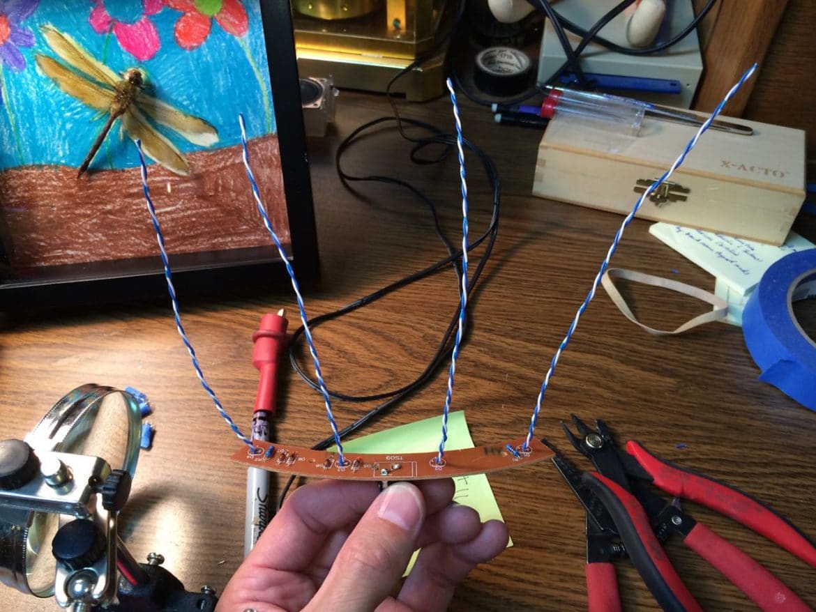
Step 3: Solder a set of wires to extend each LED.
I used some old Cat-5 cable that I saved for times like this. I was consistent in the way I hooked up the wiring and I used the dark wire (blue in this case) as the negative (-) and the white wire as the positive (+):As you can see from above, the circuit board was nicely marked so we know the polarity of each connection.
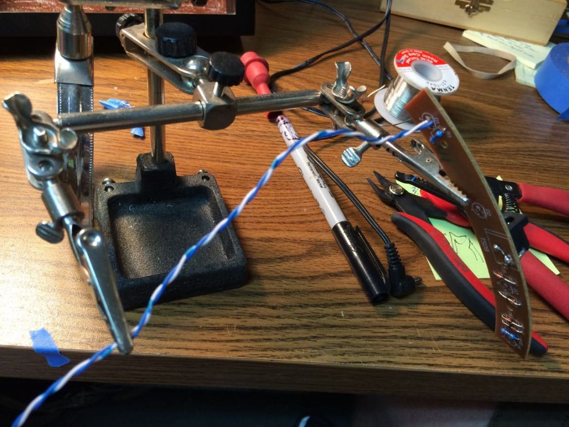
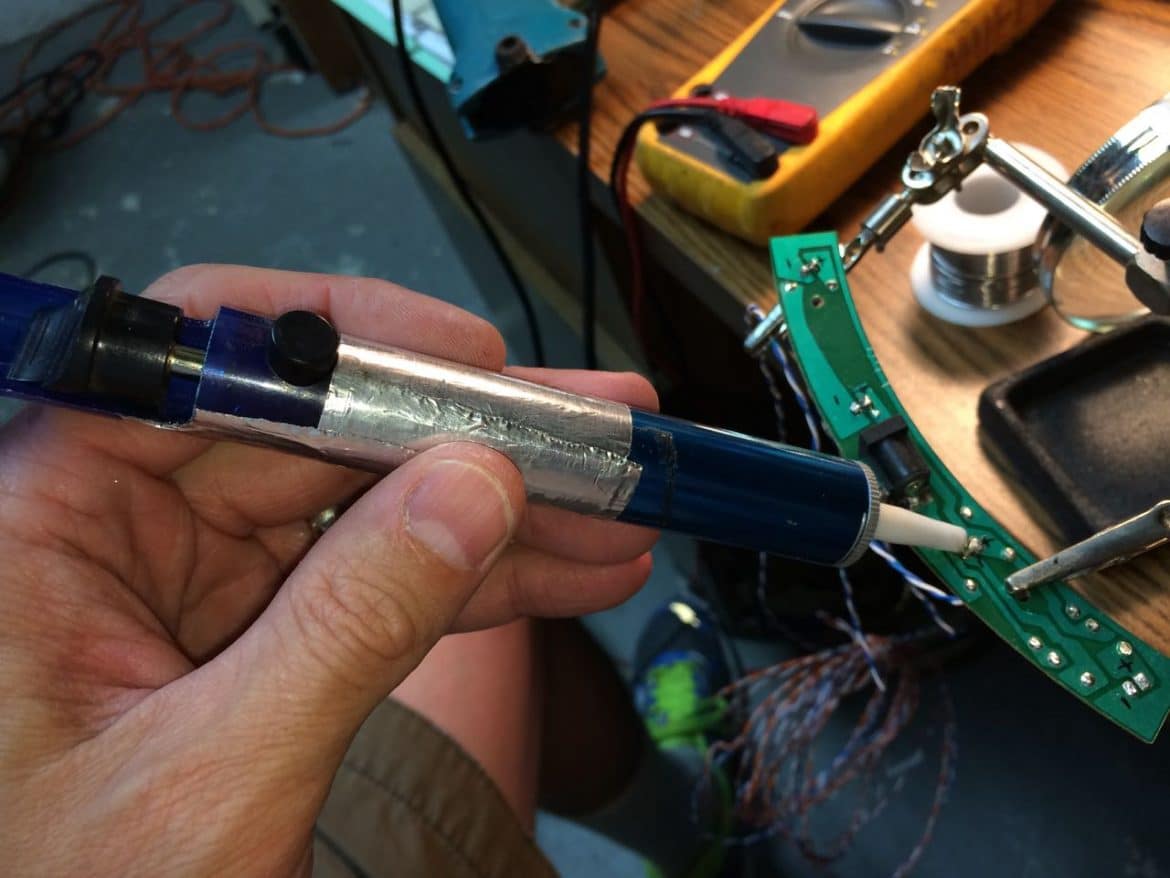
I left the wire extra long, probably 6-inches, because I didn’t know exactly how long I would need it but I did not want it too short. You may need to heat up the solder on the circuit board in order to push the wires through. This was the perfect time for me to use my extra set of hands tool:
Holding everything with my Extra Set of Hands
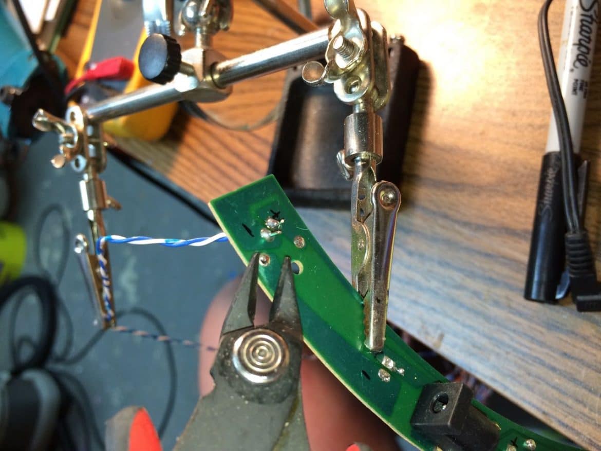
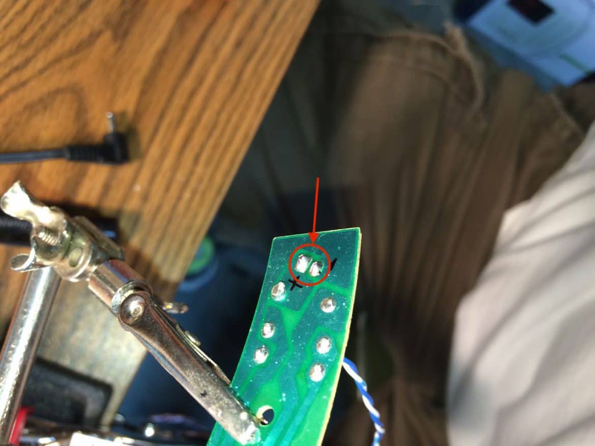
I added solder and soldered the wires in place. Then cut off the excess wire with a flush cutter (get one if you don’t have one–they are so handy). Make sure you don’t bridge the positive and negative solder joints together like I had happen here:
I simply heated up the solder and used my solder sucker to remove it:
Here’s what a good set of solder joints looks like (I had already trimmed them off with my flush cutters):
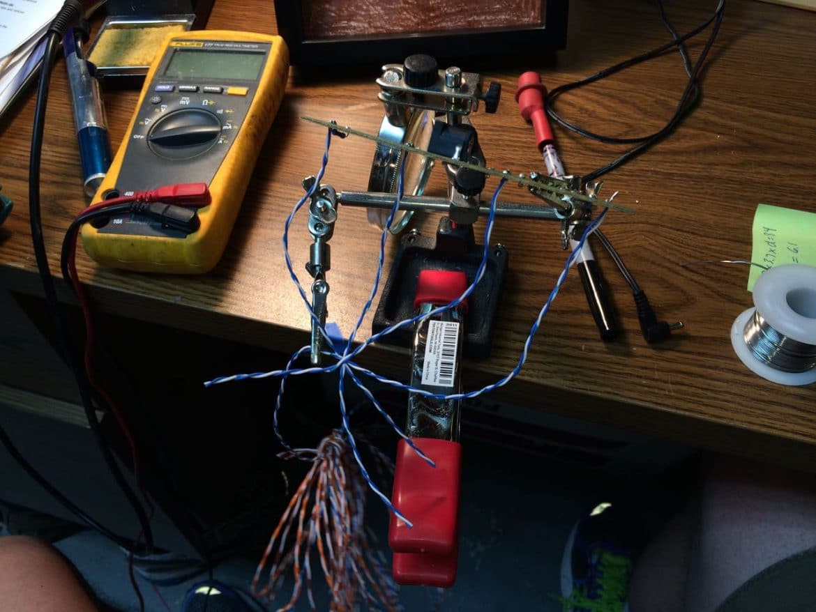
This is where I plan on mounting the circuit board and these wires will be plenty long enough for that:
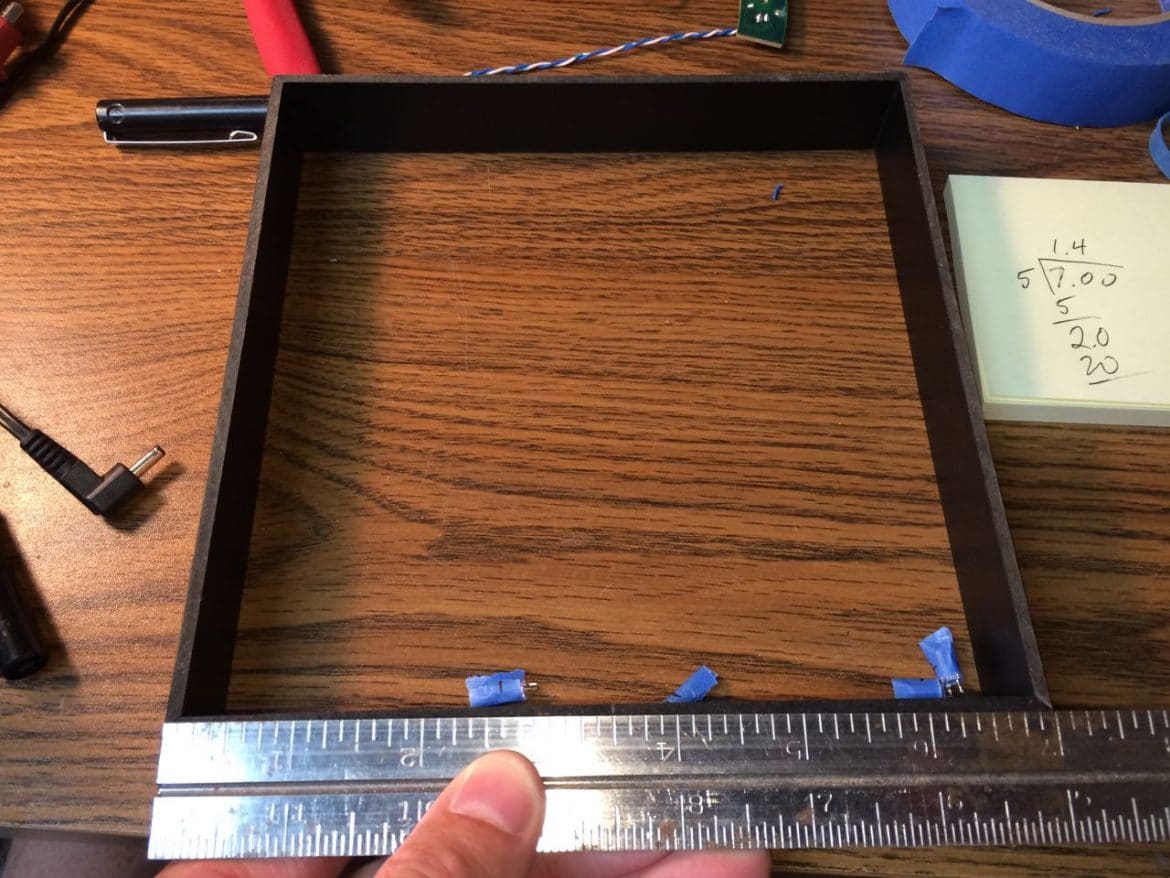
Step 4: Choose the locations for the LEDs and drill holes for the LED leads to go through.
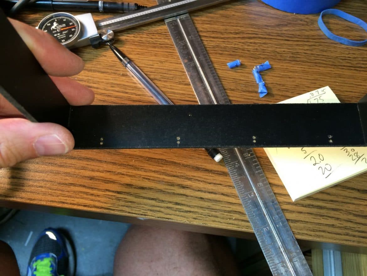
I wanted them evenly spaced. This shadow box has a spacer frame that presses the glass to the front of the frame and holds the picture against the back of the frame. The spacer was approximately 7 inches square. That gives me a spacing of about 1.4 inches. I measured the center and then went left and right from there:
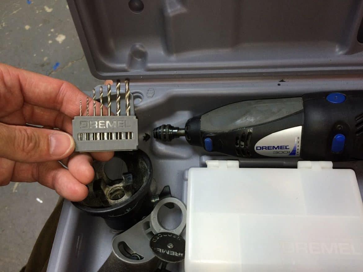
Step 5: Drill holes for the LED leads to pass through.
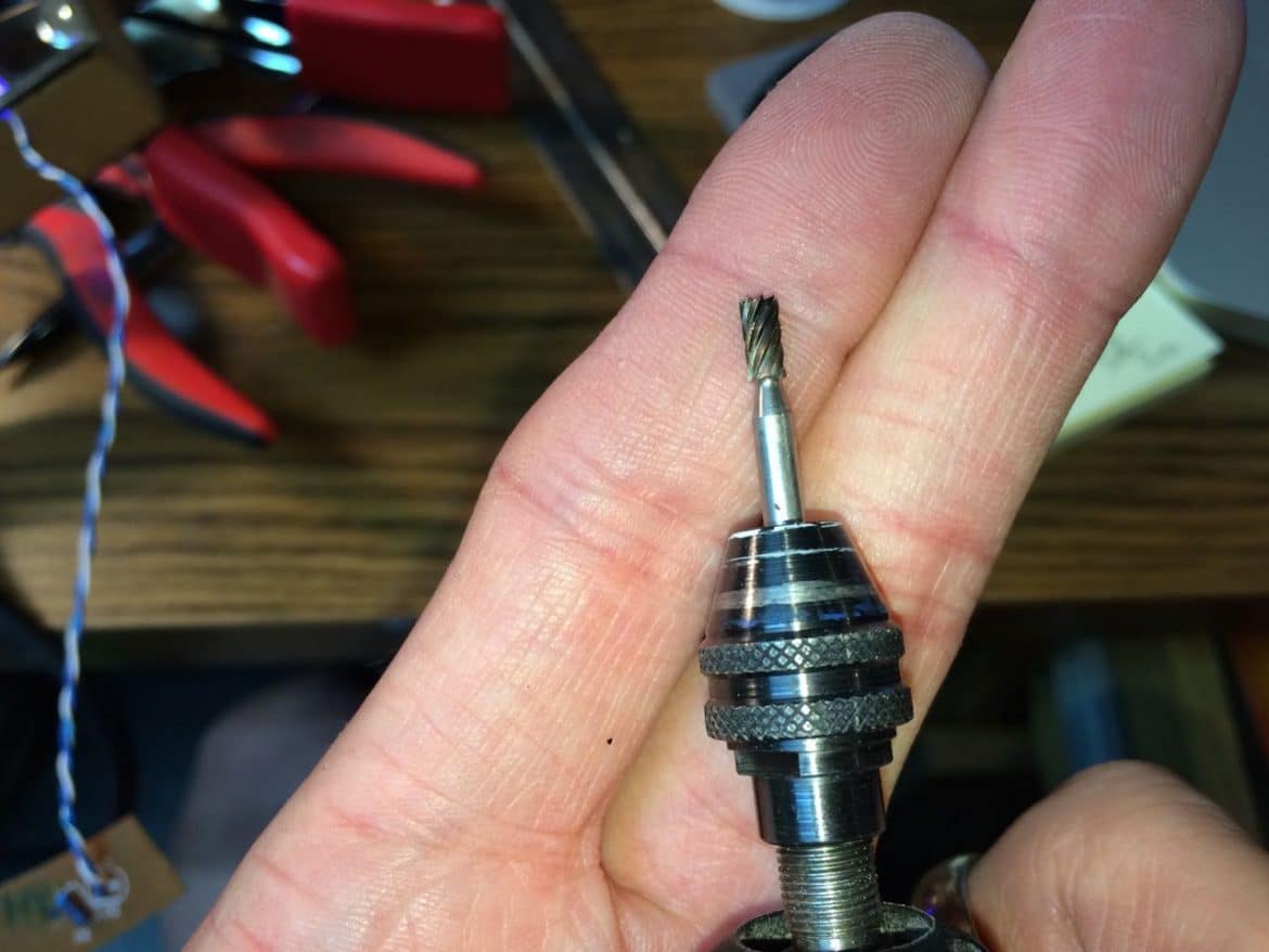
I used my Dremel Tool with Keyless Chuck
(which is required for these small bits):
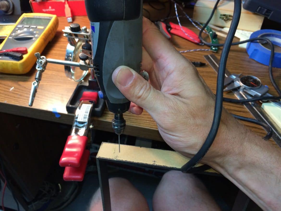
Below you can see the holes drilled. If I make another one of these I’ll probably rotate them 90-degrees so the path for both wires is straight out, you’ll see when you read the following steps.
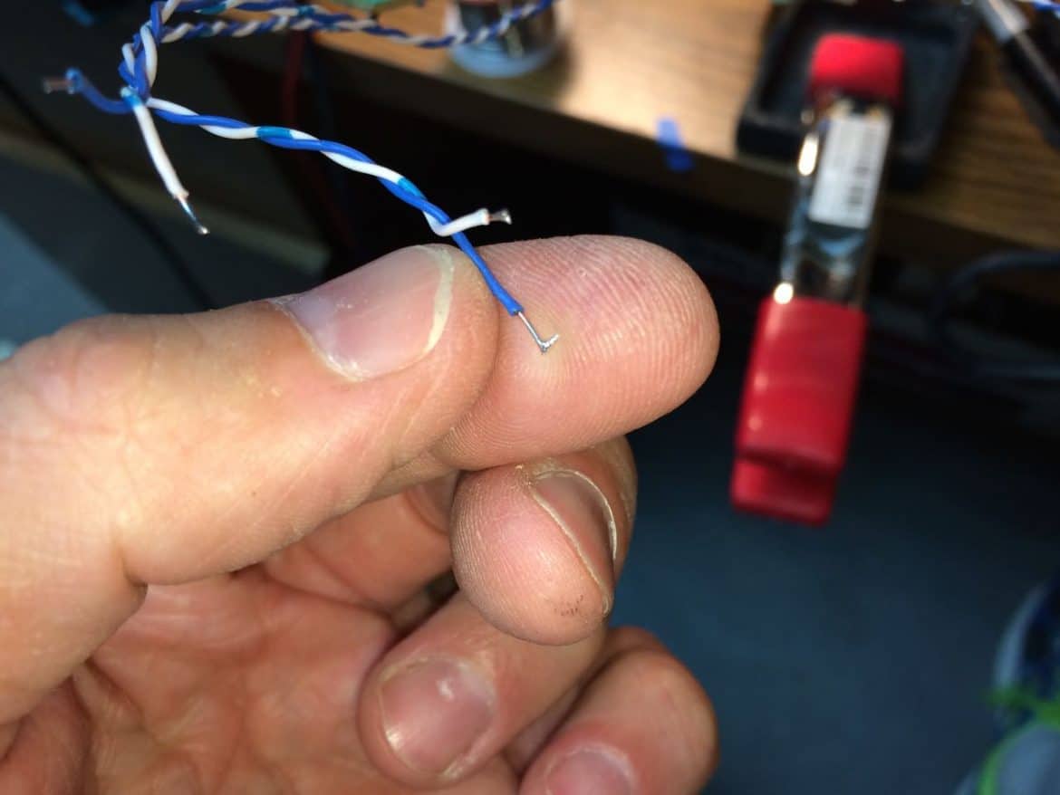
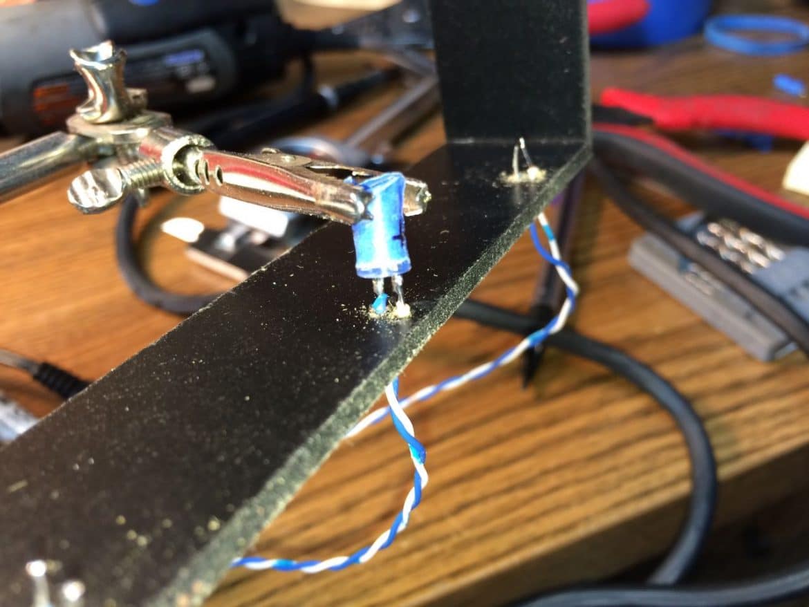
Step 6: Tin the ends of the wires you are going to connect to the LEDs.
It’s going to be tricky to solder the wire to the short leads on the LEDs and not overhead the LED by keeping the soldering iron on there for too long. Put some fresh solder on each of the wires, which will ready them to connect to the LED leads. Be careful not to leave a big glob of solder on them though, or they won’t fit through the hole:
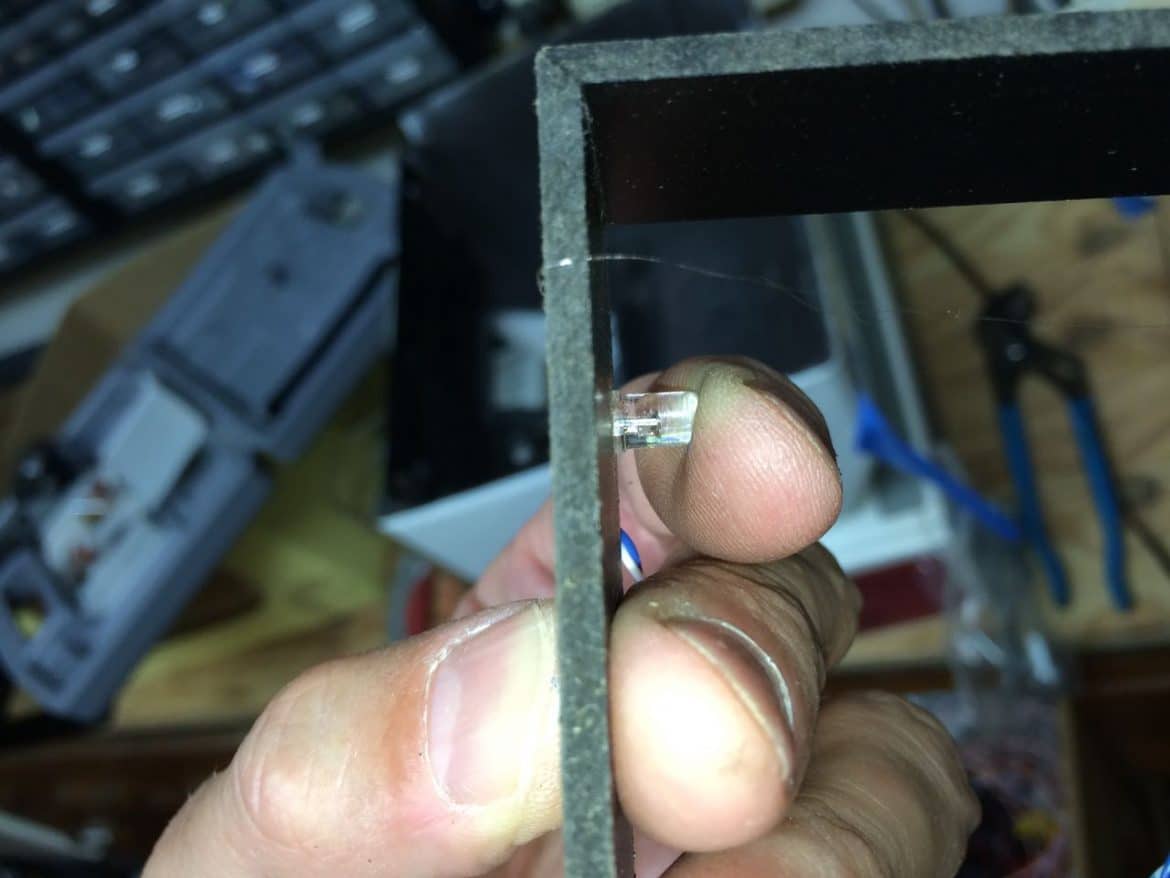
Step 7: Feed the wires through the holes in the frame and solder the wires to the LEDs.
Make sure you keep track of the polarity of the LEDs and connect the positive to positive:
Don’t use too much solder, it doesn’t take much. The fresher the solder the better (ie you just melted it off the spool and there is flux mixed in with it). Here’s a picture of all the LEDs soldered:
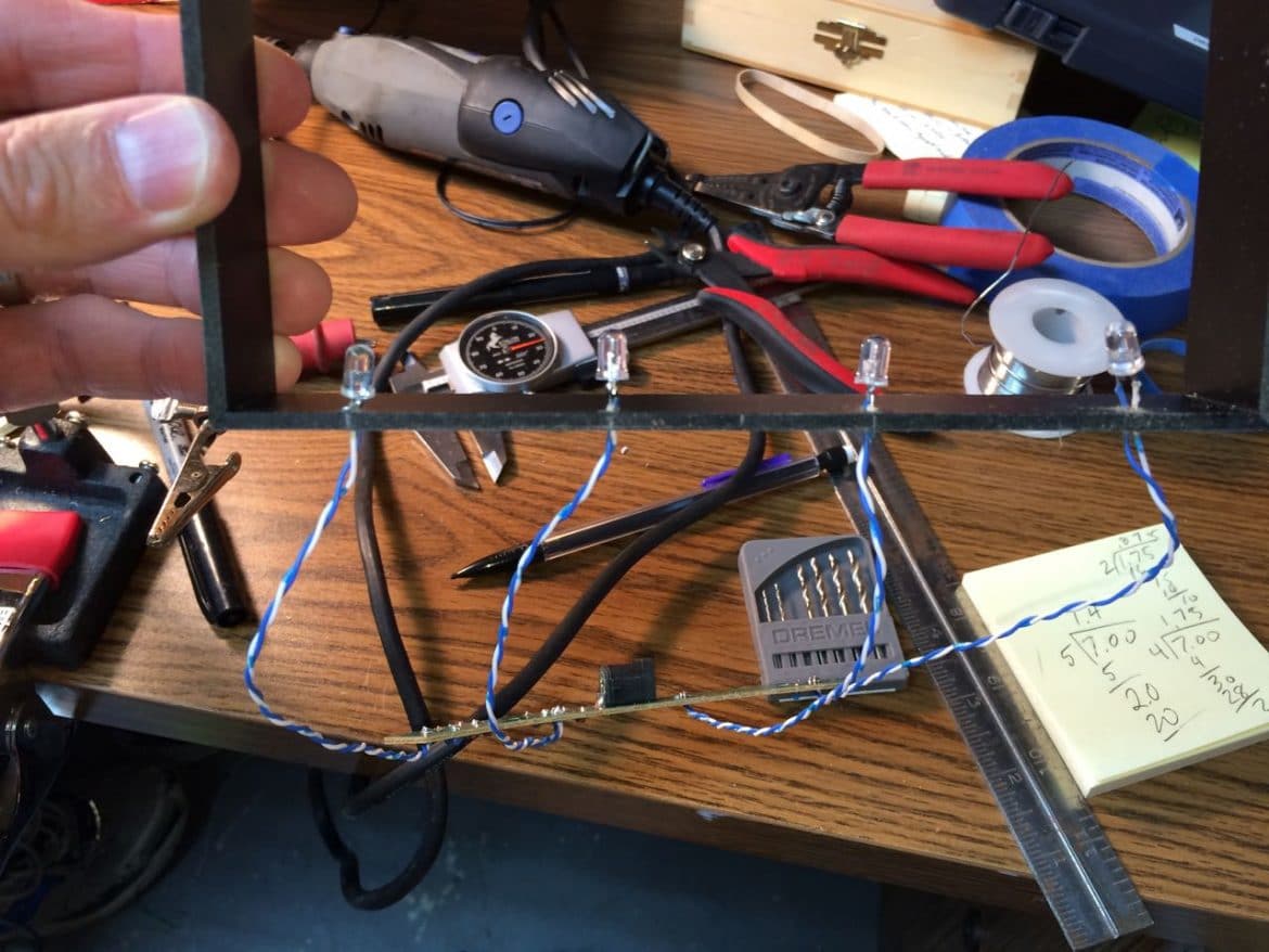
Step 8: Test the LEDs.
Double check your wiring first and then power it up to make sure everything is good. Here’s what mine looked like:
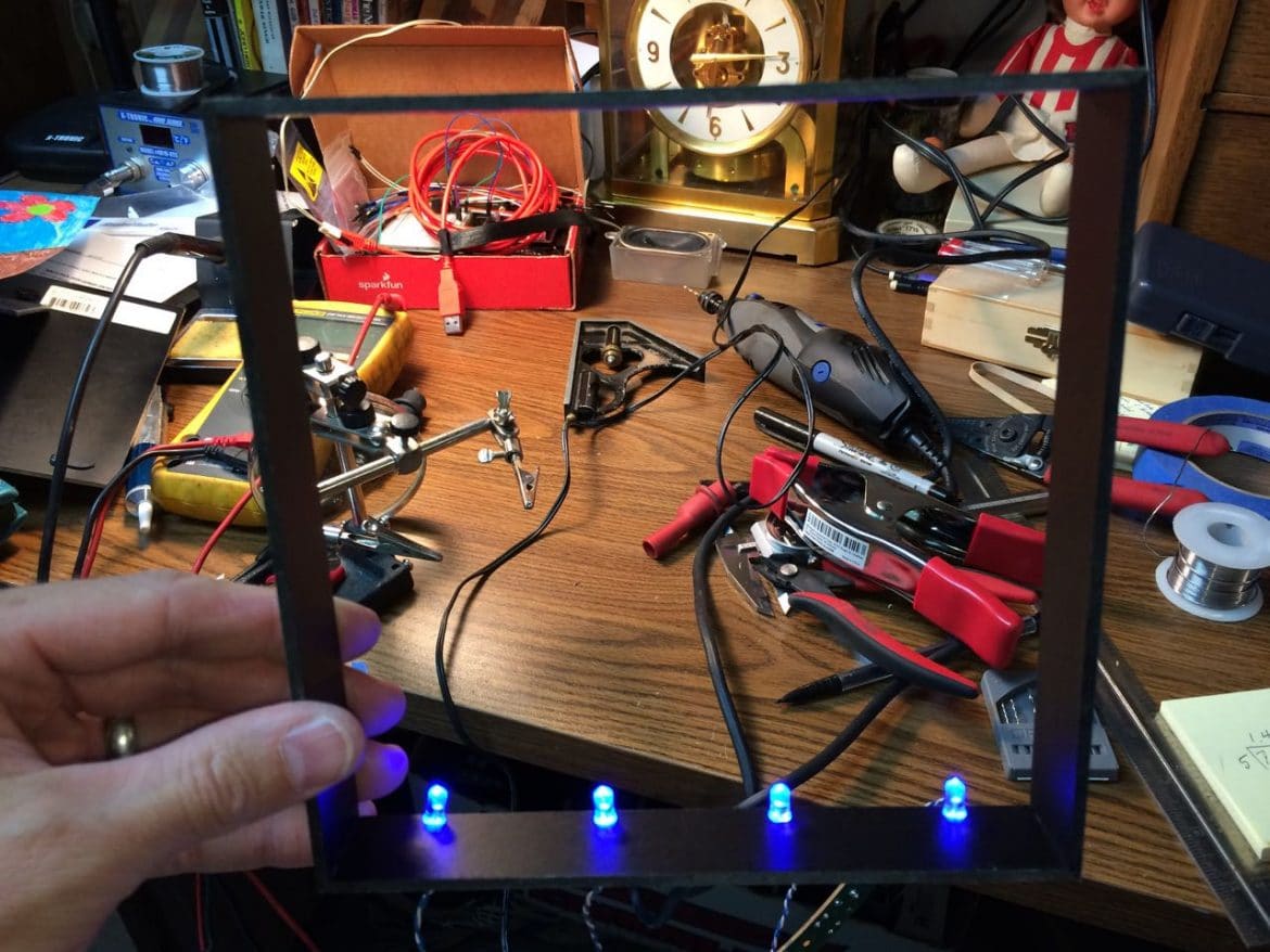
And with the spacer slipped in the frame:
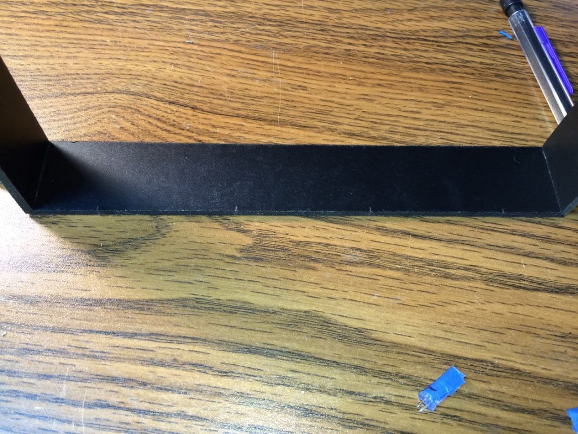
Step 9: Create a path in the spacer frame for the wires to run out.
I cut a little path for each wire to get to the back:
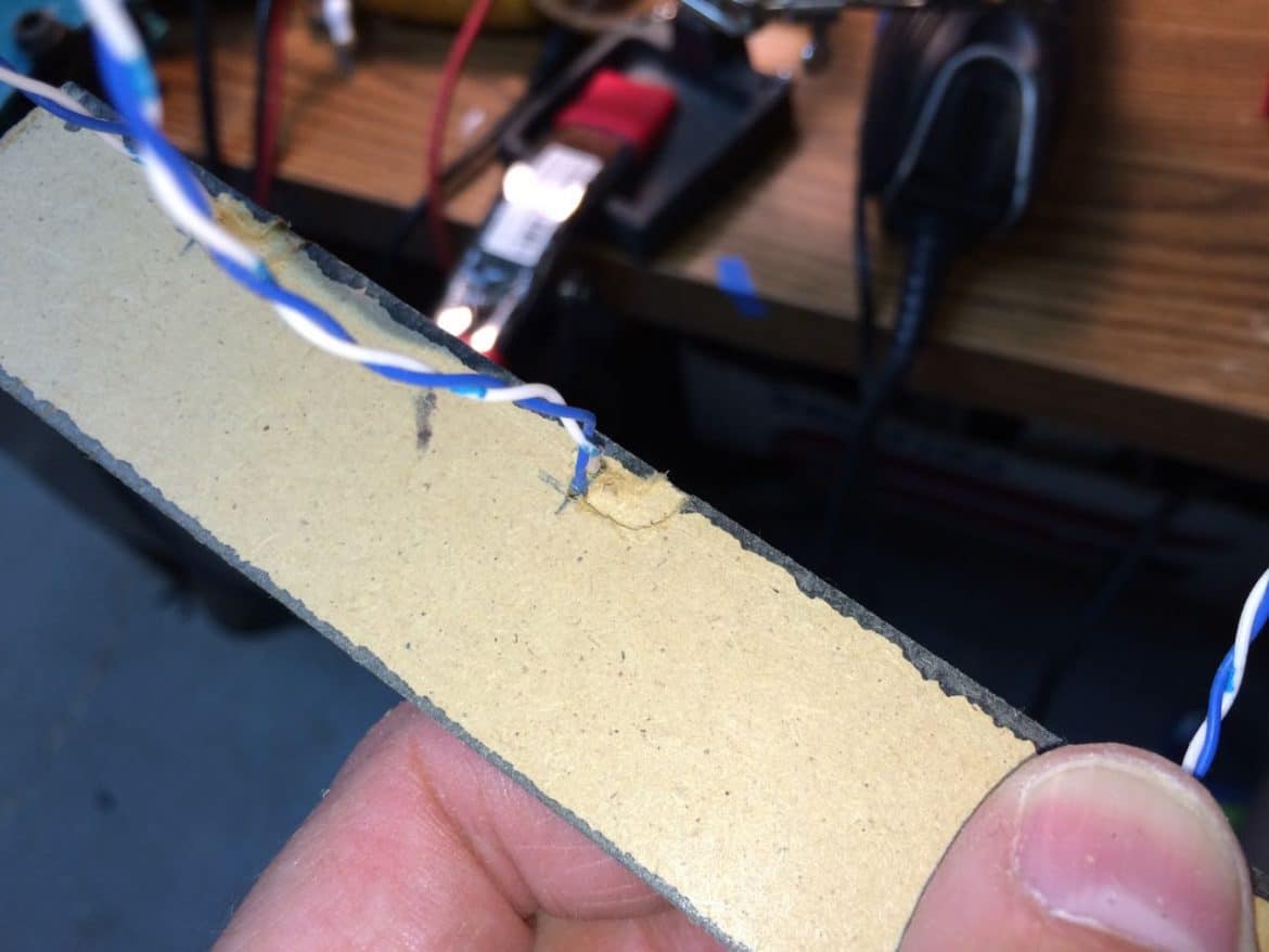
With the spacer frame in place I marked where I needed to notch the back out and then cut some notches so the wires could get out:
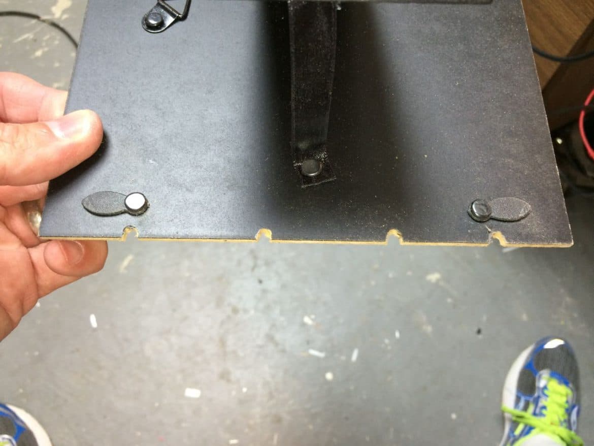
I then installed the spacer and the back, with the wires running out the notches:
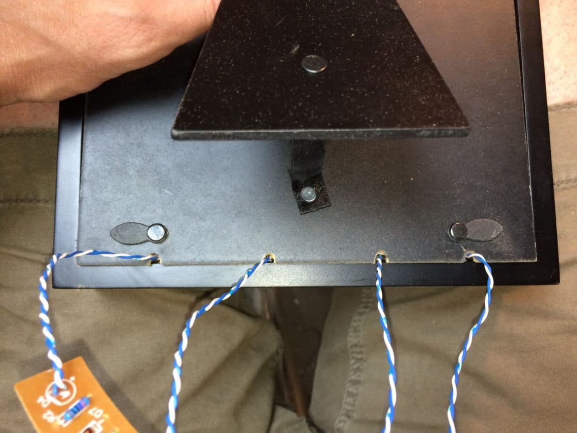
And this is about where the circuit board will be glued in place:
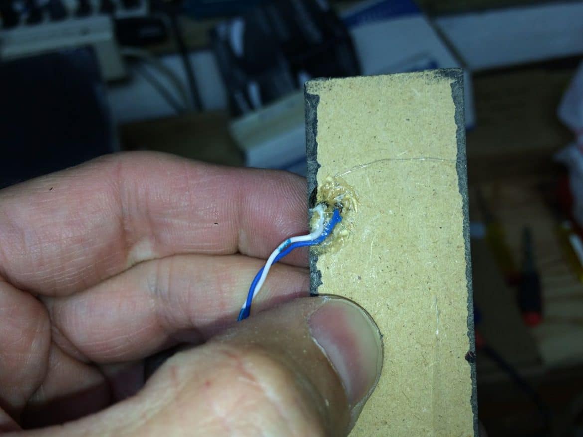
Step 10: Glue the wiring in place to hold the LEDs straight.
I installed the spacer frame in the outer frame but the LEDs pointed in every which direction since nothing was holding them in place. Because I located the LEDs close to the picture, they appear like little spotlights on the picture and so it really matters that they are all straight. If you place yours farther away from the picture it may not matter as much. Push the LEDs tight down in their place when you are gluing the wiring so it will hold the LED in place:
Then hot glued the wires, one at a time, in the channel, to hold them in place:
Three down and one more to go:
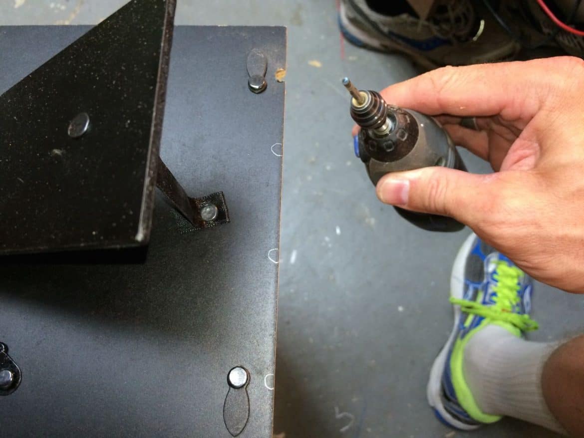
Step 11: Router out a spot for each LED’s glue glob so the spacer frame isn’t bowed up.
When I put the spacer frame inside the outer frame, with the newly glued LEDs in place, the extra thickness the glue creates caused the spacer frame to bow up in the middle. So I used my Dremel router bit to make some space:
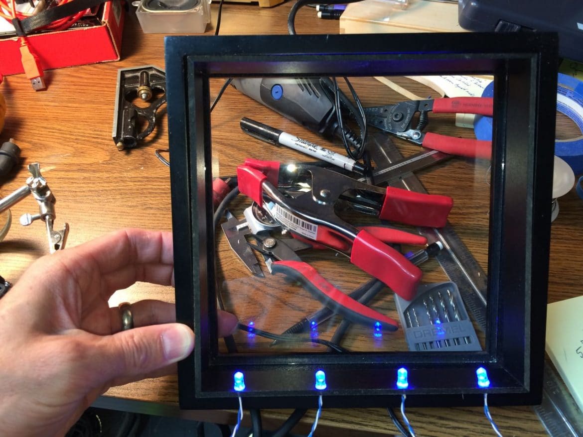
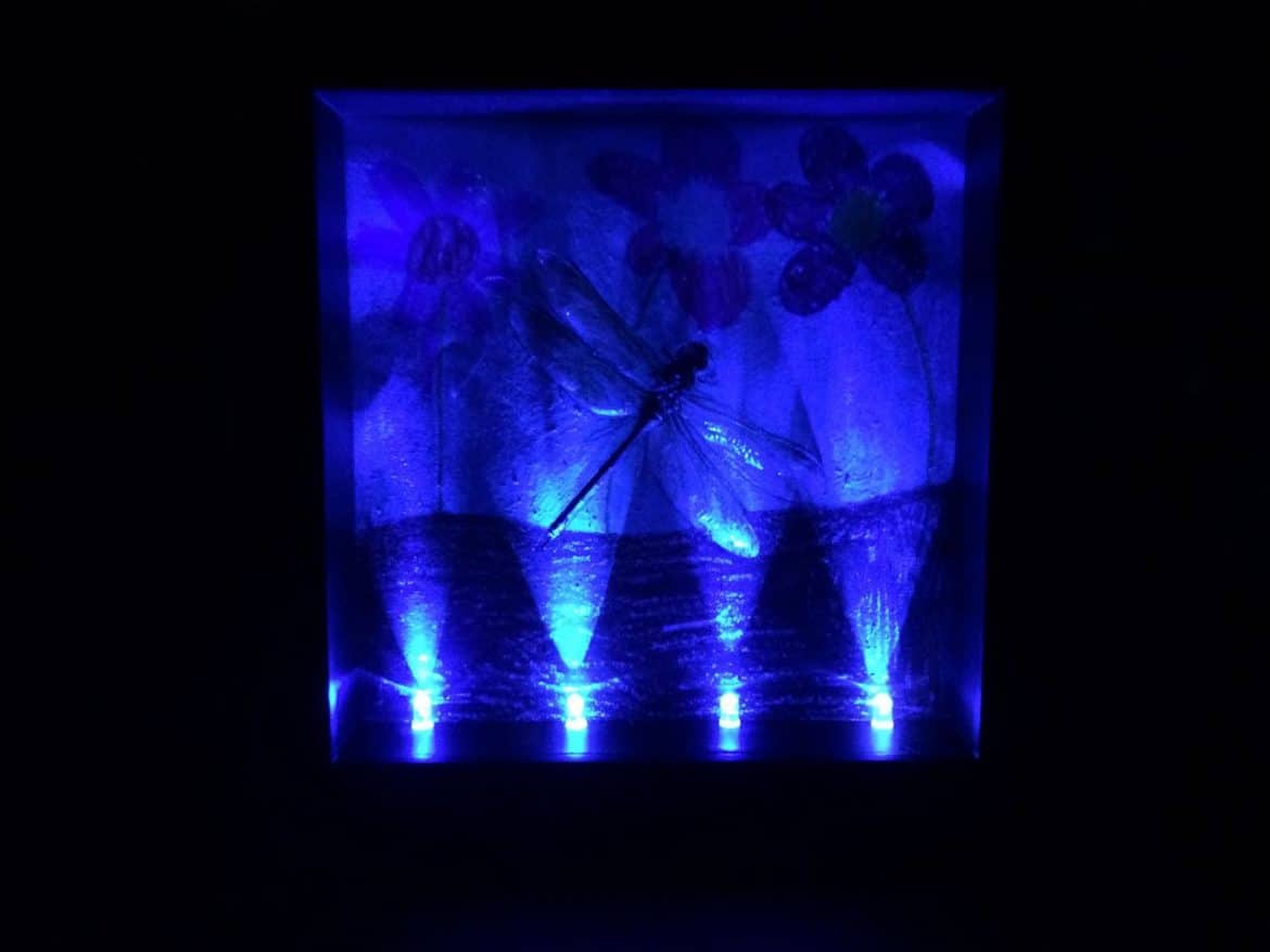
Step 12: Test out the LED-lit frame.
It is looking great:
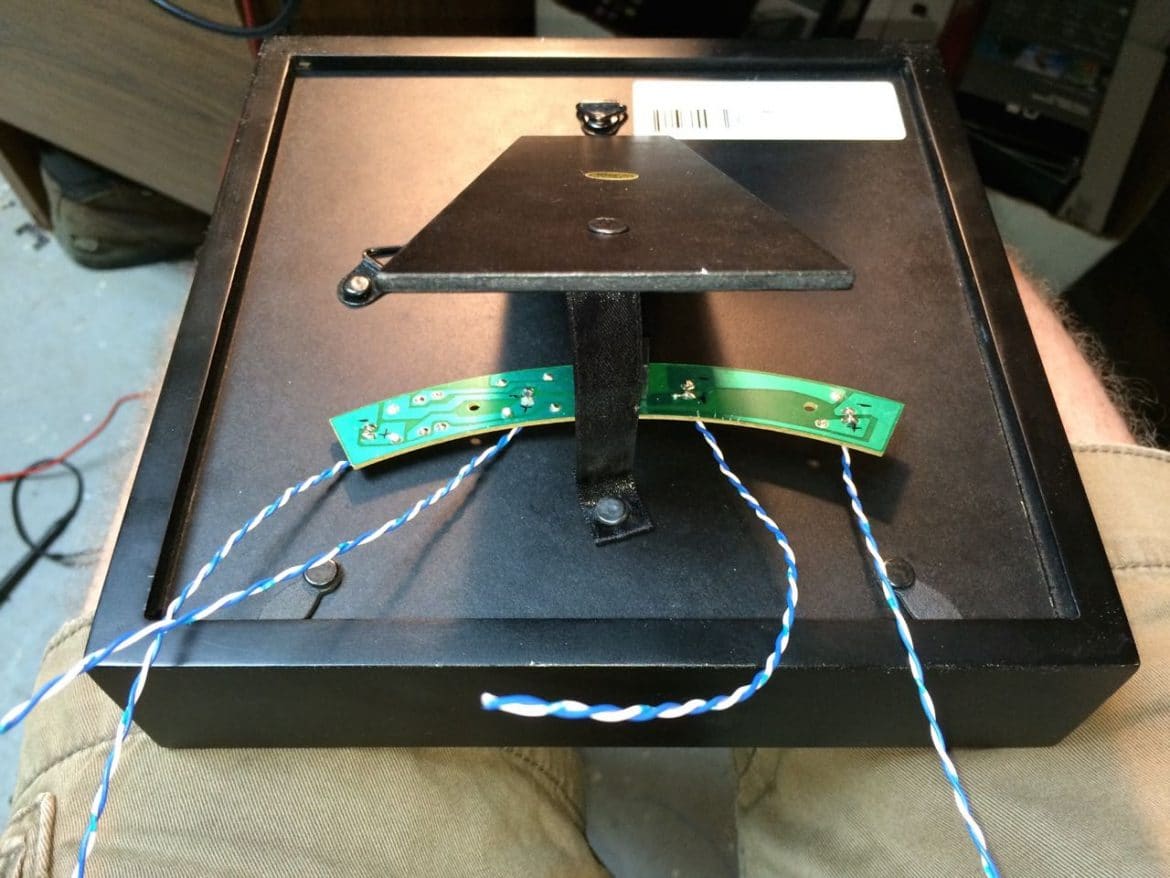
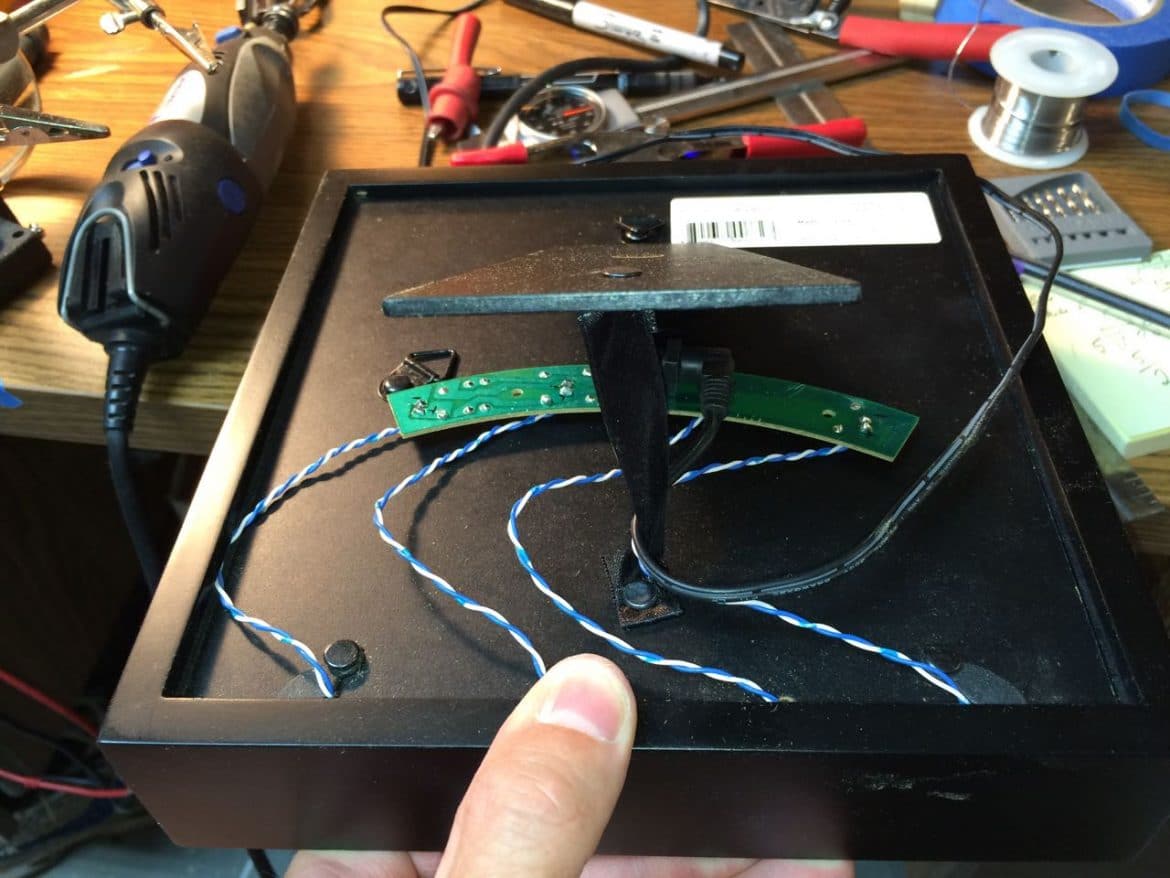
Step 13: Hot glue the LED driver circuit on the back of the frame.
Take note of how the cord will connect to the circuit board (so it hangs down in a good place and doesn’t naturally get pulled out of the socket). Now that everything is working I glued the circuit board on the back of the frame. Leave enough slack in the wires so you can take it apart again (to clean the glass for example).
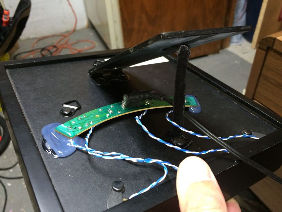
It’s not going anywhere 🙂
The finished product:
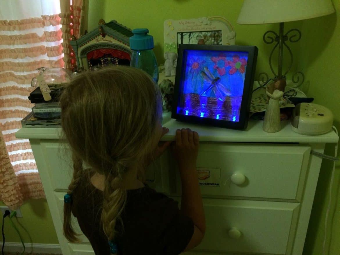
Step 14: Give it away.
It’s so fun to feed your kid’s imagination and have fun doing it! My daughter loves it. It even looks neat when the lights are on:
Amazon Associate Disclosure: As an Amazon Associate I earn from qualifying purchases. This means if you click on an affiliate link and purchase the item, I will receive an affiliate commission. The price of the item is the same whether it is an affiliate link or not. Regardless, I only recommend products or services I believe will add value to Share Your Repair readers. By using the affiliate links, you are helping support Share Your Repair, and I genuinely appreciate your support.