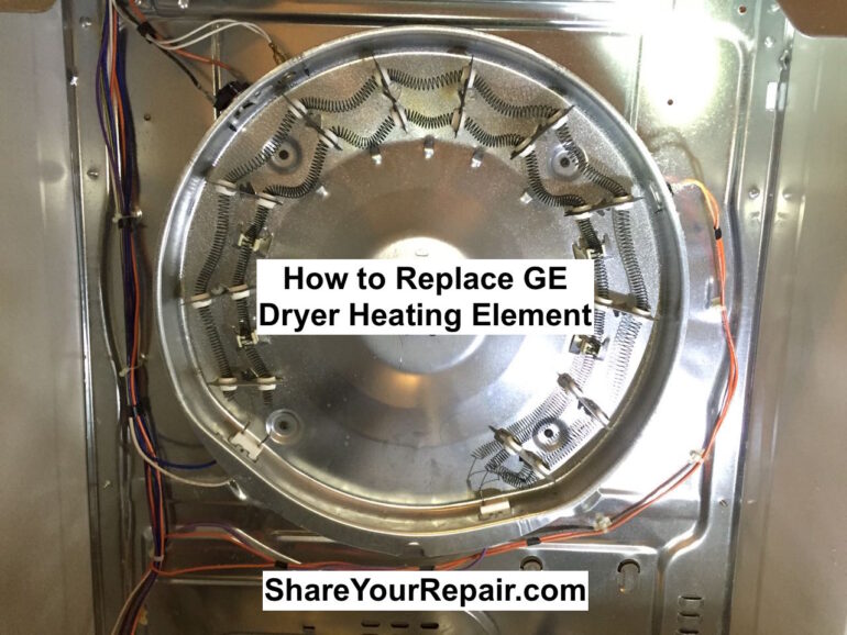
If you are having issues where your dryer will not heat then you should focus on the heating element assembly. The heating element could be bad or the safety thermostat, the inlet control thermistor, or the safety thermostat–all which are mounted on the heating element assembly. Follow along and I’ll show you how to tear your dryer apart and replace the heating element…
How to Replace Heating Element on GE Dryer
Equipment:
Parts Needed:
Tools Needed:
- Phillips Screw Driver
- PZ2 Phillips bit, get both of these in a 100 Piece Tamper Security Bit Set (Metric and SAE Standard)
- Cordless Screw Driver
- Pliers
(to remove electrical connectors on the heating element)
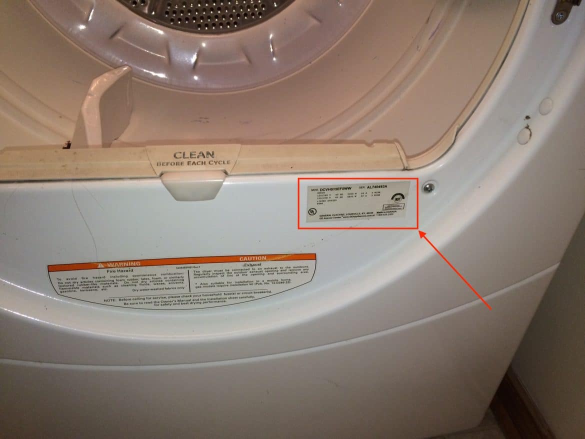
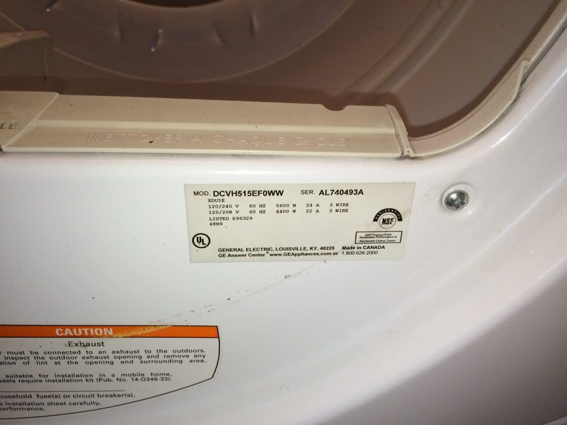
How to determine your GE Dryer model: Open the door and look at the bottom right edge of the dryer’s opening:
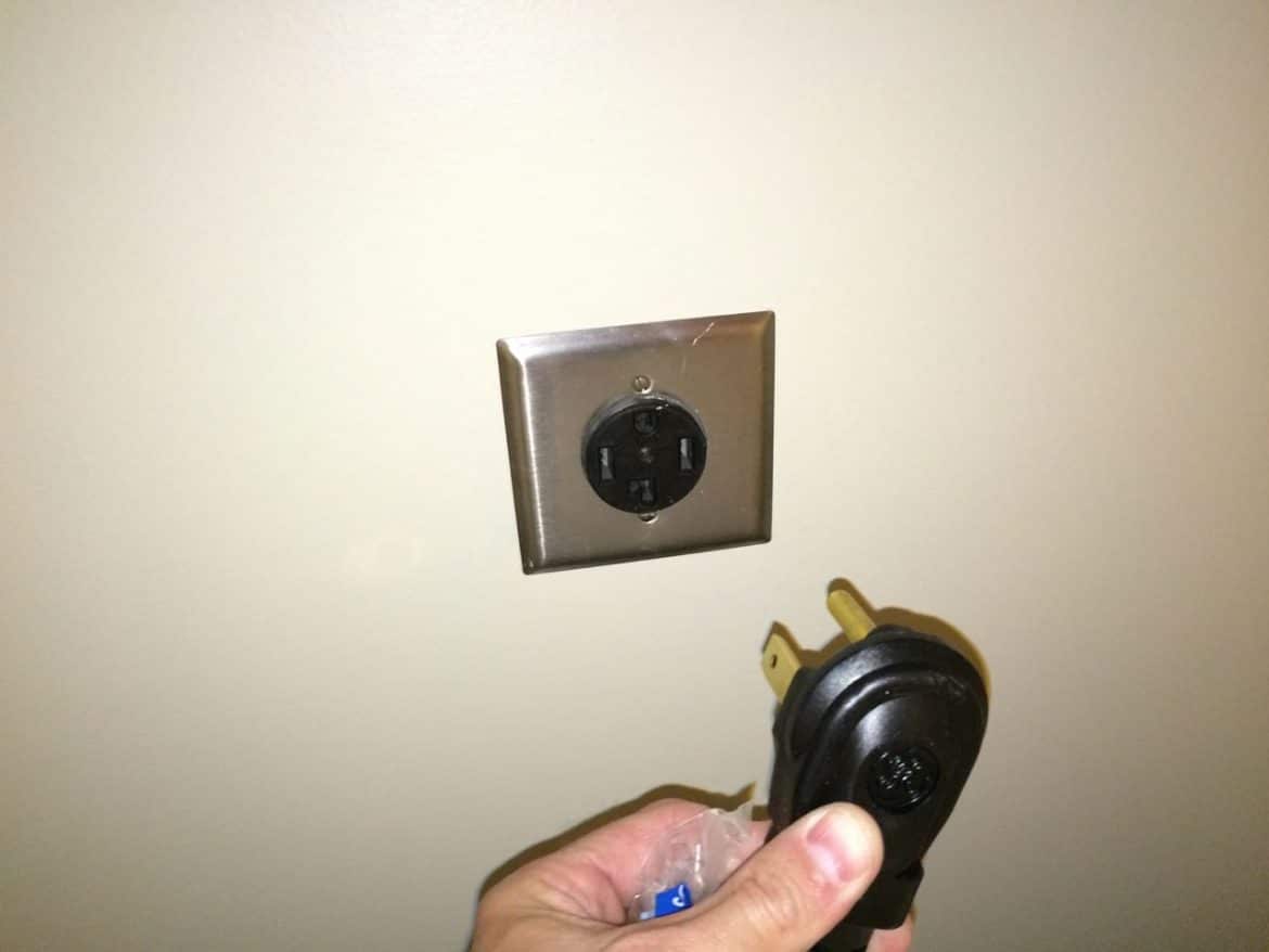
Step 1: Unplug your dryer.
If it is an electric dryer like mine you are dealing with 220V. Regardless, make sure to unplug it before working it on so you don’t get electrocuted.
Step 2: Remove the 3 Phillips screws on the top edge of the back of the front bezel.
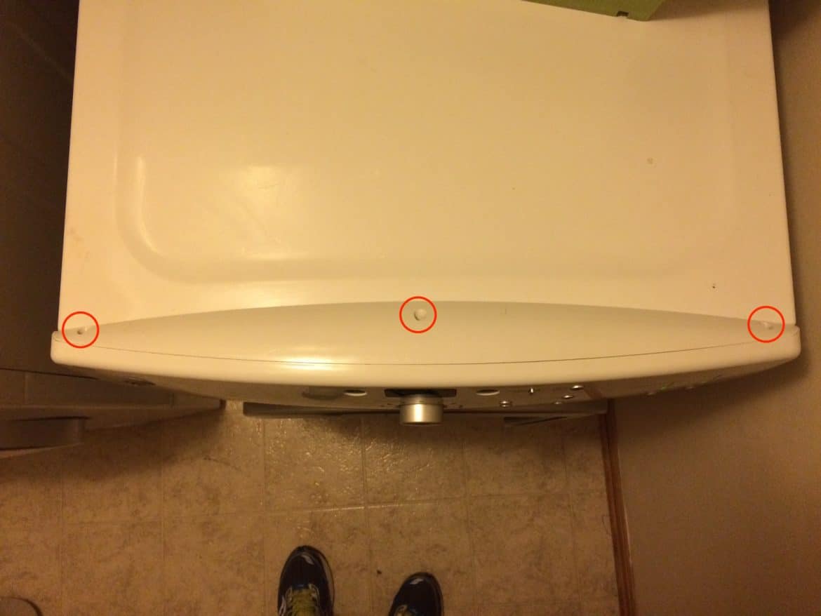
Once you have removed those three screws you can put your fingernails in the seam and slide the bezel toward the back of the dryer.
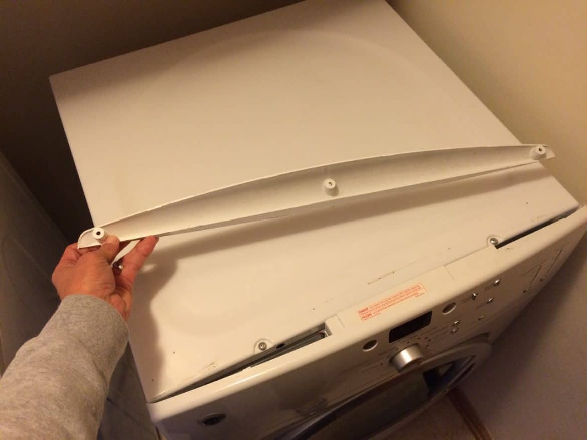
Set the bezel and the three screws aside.
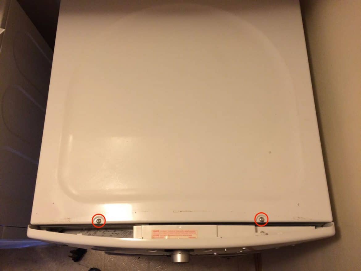
Step 3: Remove the top two cover screws.
They are Phillips head screws:
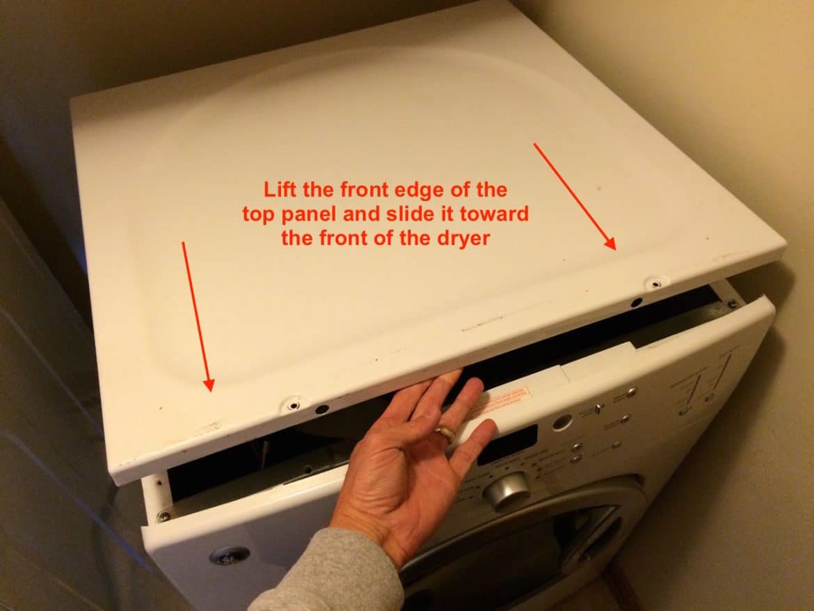
Step 4: Remove the top panel.
Lift up the front edge of the top panel and slide the panel toward the front and remove the top panel.
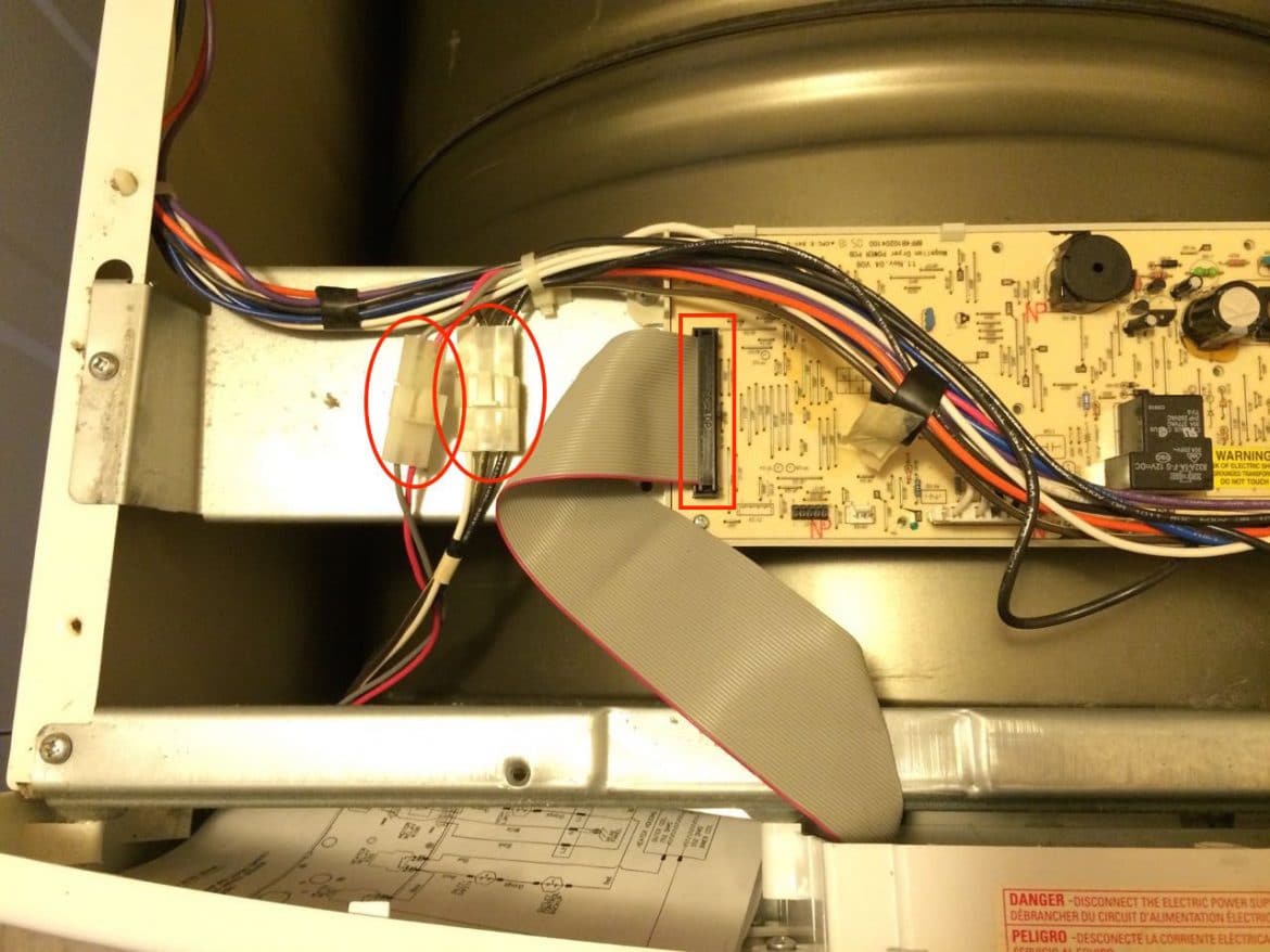
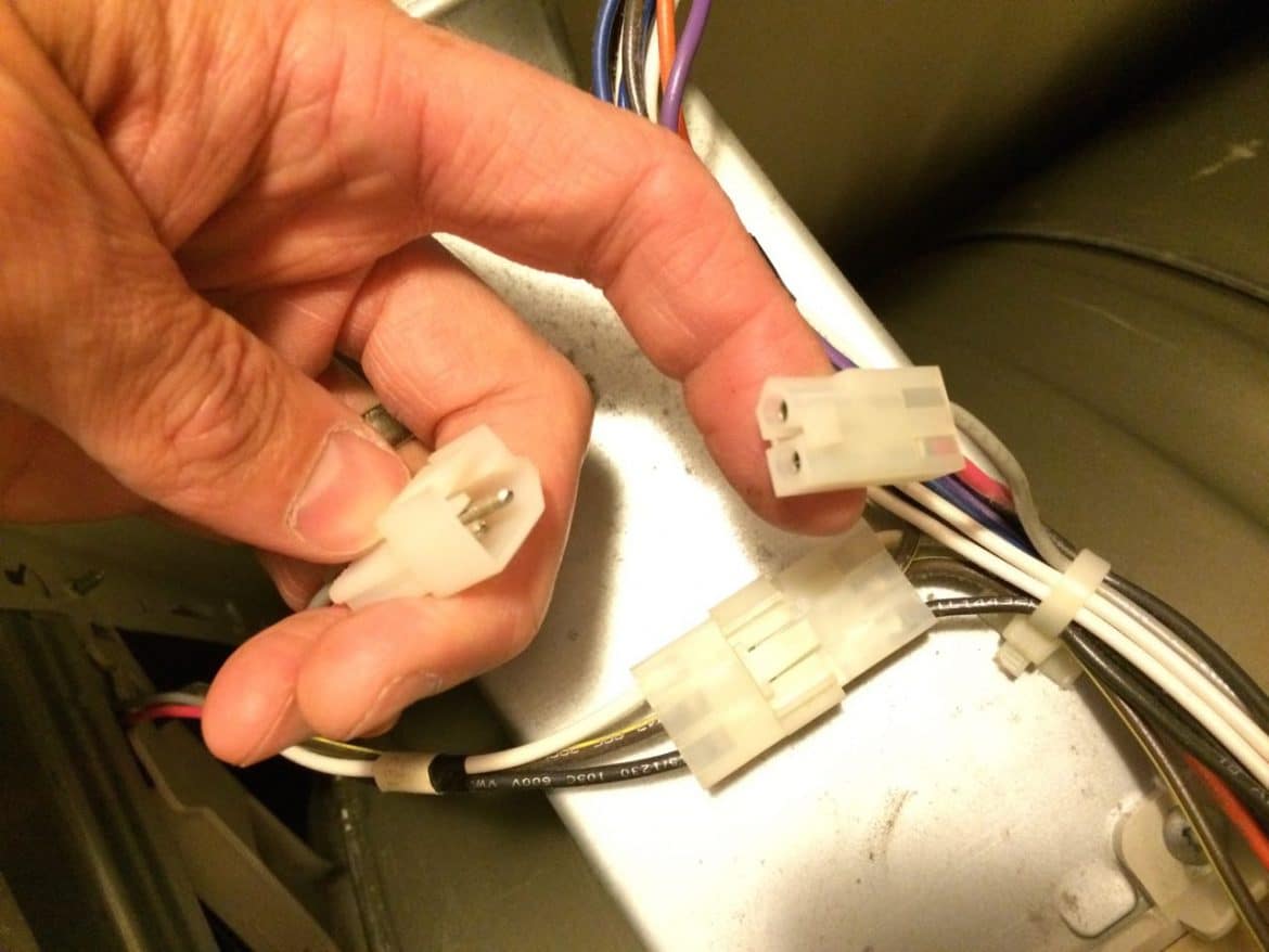
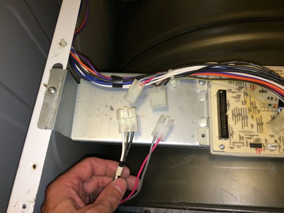
Step 5: Disconnect the light, switch, and control panel wiring connectors.
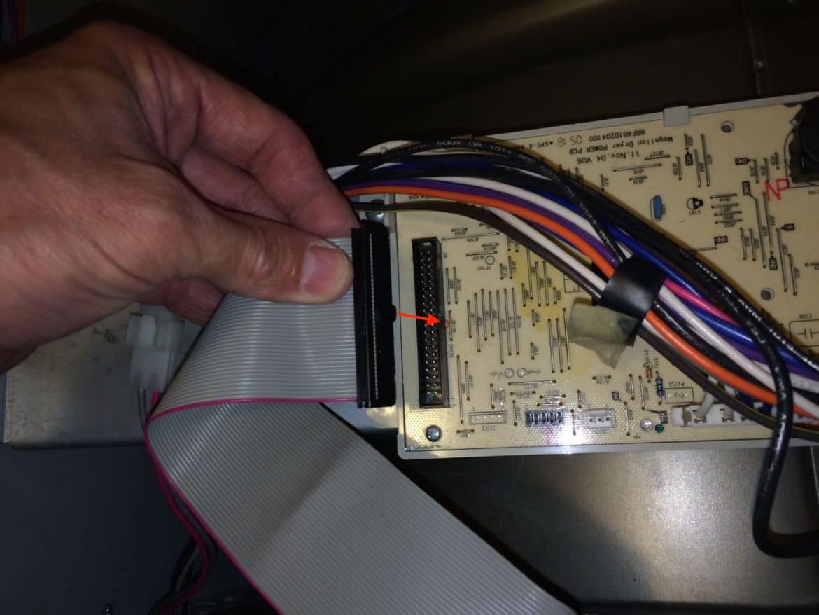
Before you proceed you need to disconnect three wiring connectors. One is a parallel computer-type ribbon cable for the controls, one is for the light, and the other is for the door light switch (the latter two have tabs you must lift in order to disconnect them):
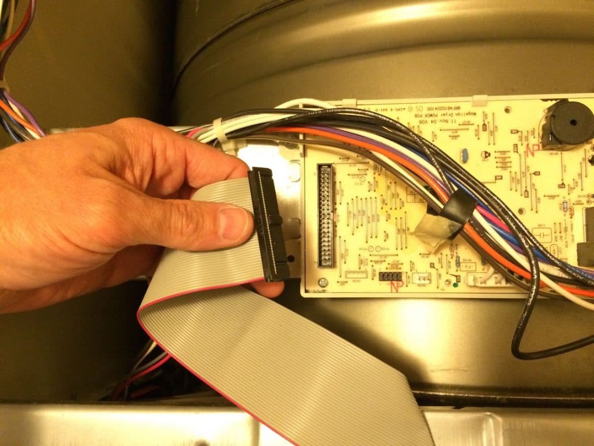
I put one finger on the left side under the ribbon cable and the other on the right side of the black connector, wiggling the connector and pulling up to remove it. Be careful because you can actually pull this ribbon connector apart. I’ve taken my dryer apart about 4 times now and one of the clips on the end that holds the black connector together has begun to come apart. Be gentle and wiggle the connector around as you pull up.
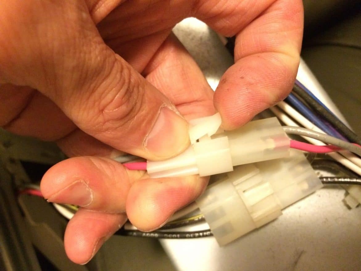
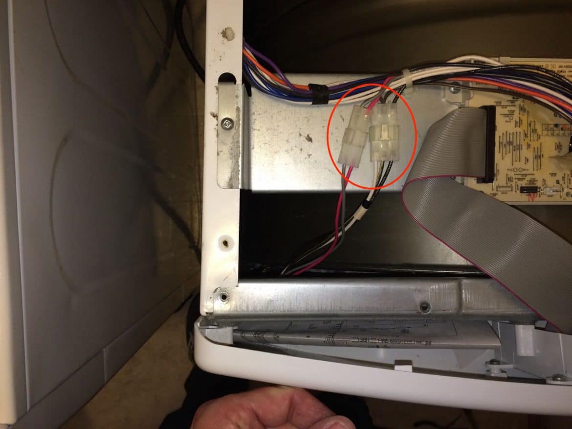
The other two connectors are a similar style where you must lift up the “catch” and pull them apart as shown below:
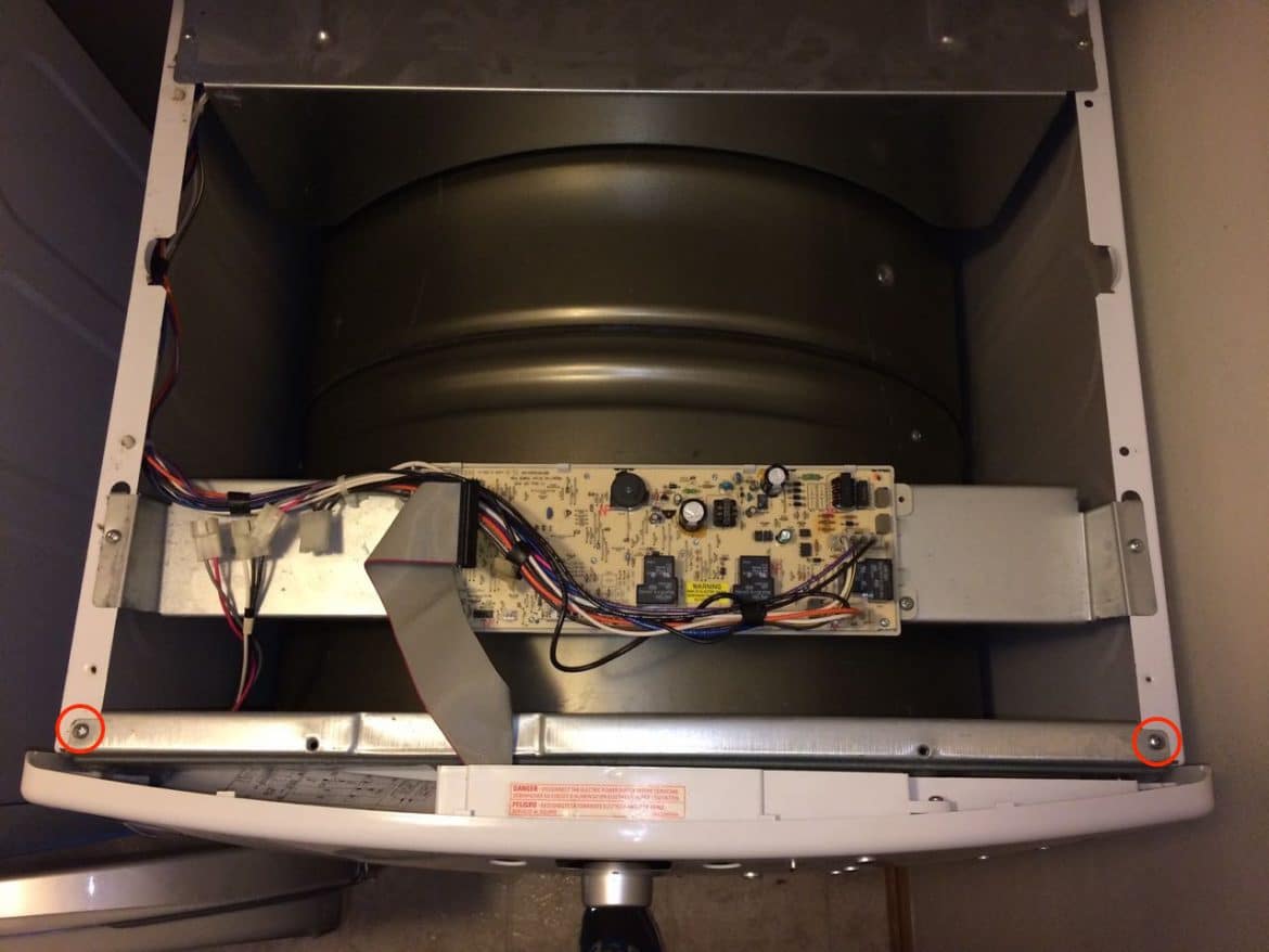
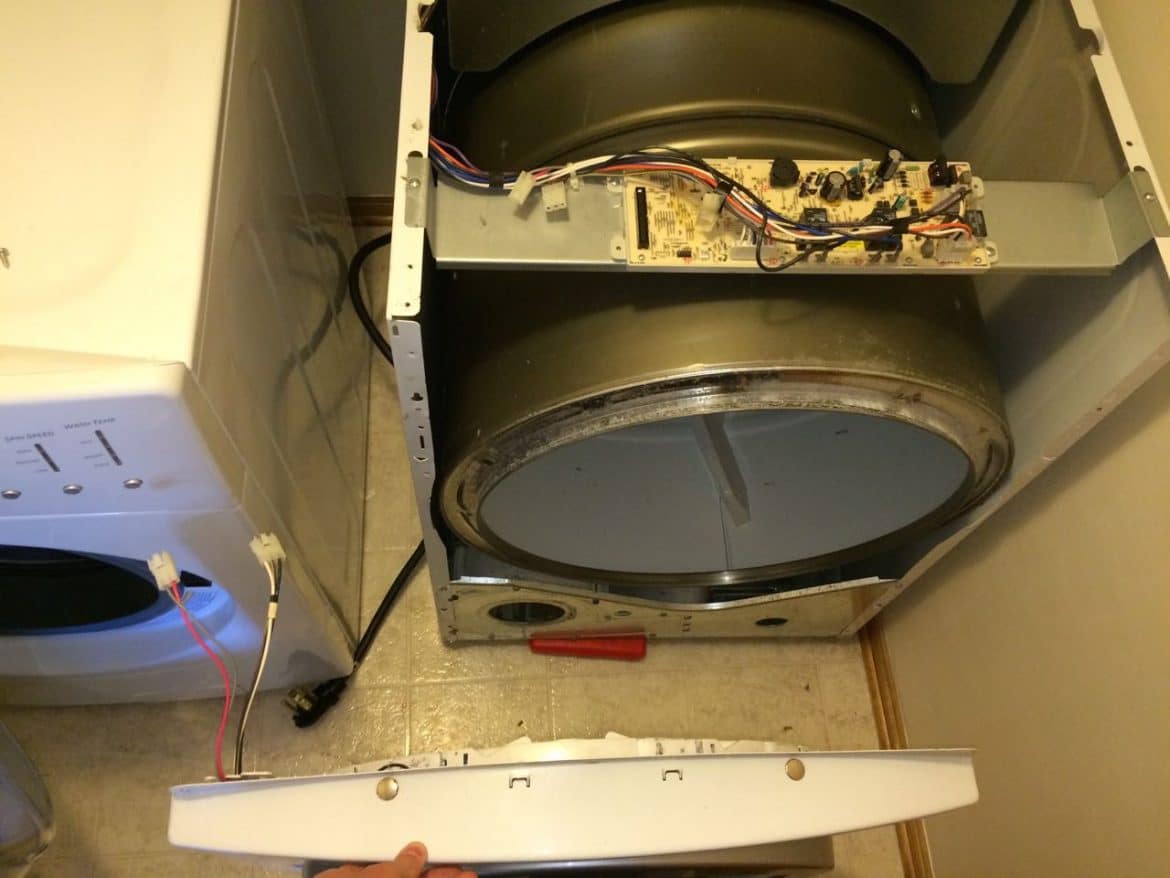
Step 6: Remove the control panel.
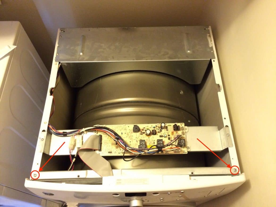
Remove the two top control panel mounting screws:
Then lift the control panel up and off:
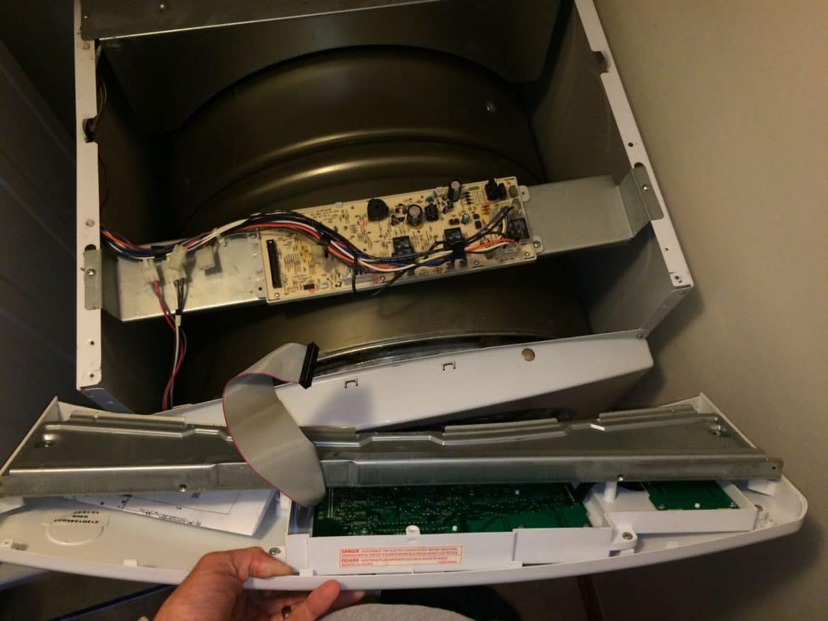
Set the control panel aside in a safe location.
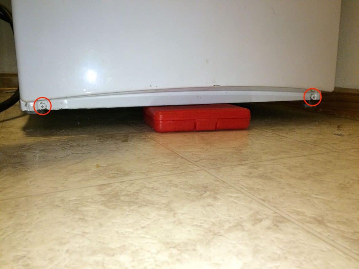
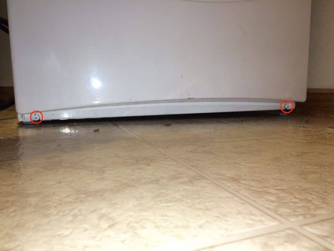
Step 7: Loosen the lower front panel screws.
I found it easier to get at them by propping the front edge of the dryer up on my screwdriver case as you can see below. Loosen, but do not remove, the lower front panel screws. If you don’t loosen them enough, almost a quarter-inch, you will not be able to lift the panel up and off of them (I ran into that issue).
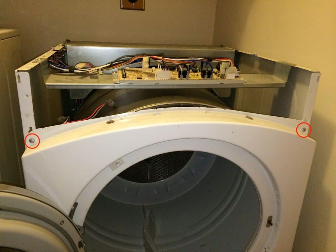
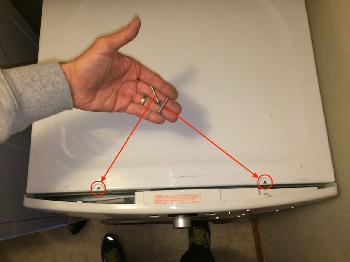
Step 8: Remove the upper front panel screws.
Remove the two Phillips screws from the upper front panel:

Once you have removed the upper front panel screws you will want to hold the front panel on to the dryer and swing shut the dryer door.
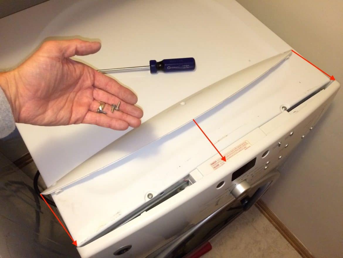
Step 9: Lift the front panel up and off the dryer.
Lift the front panel up and off the two lower screws that you loosened in Step 7. Be careful because the door will want to swing open (which makes the front panel want to fall forward then).
Here’s another view:
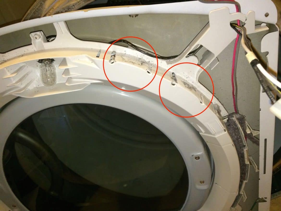
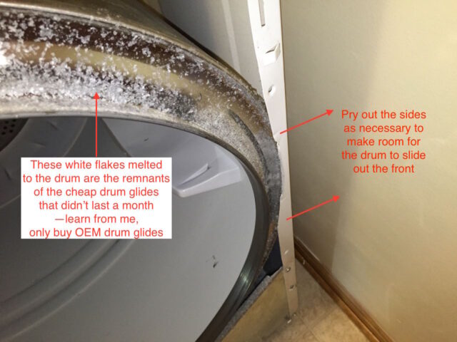
Step 10: Turn the front panel around and inspect the four drum glides.
While you are in here you should take a look at the drum glides. The drum guides are shown by the arrows in the picture below:
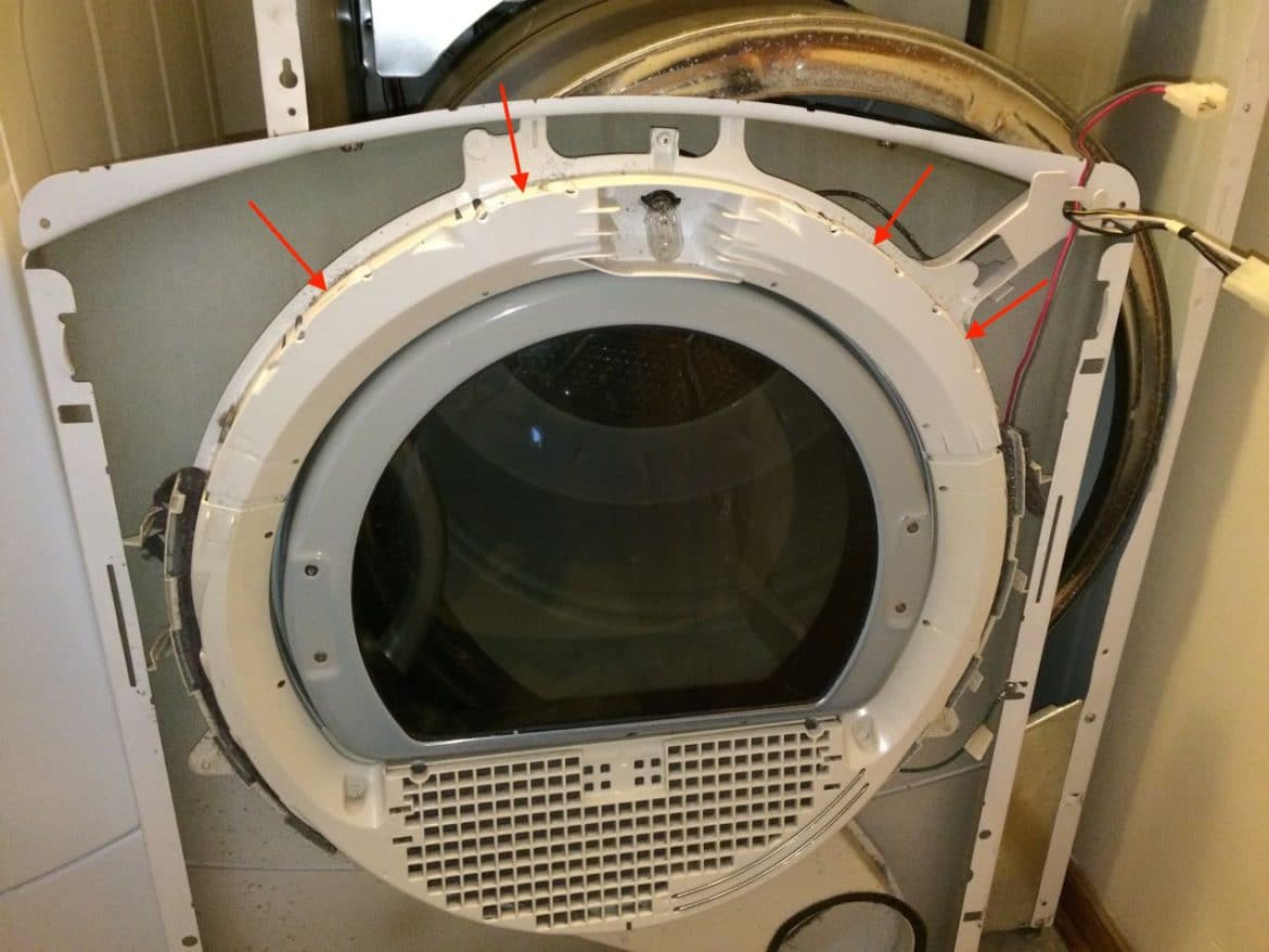
This is what good OEM drum glides should look like, the top two should be of a darker material:
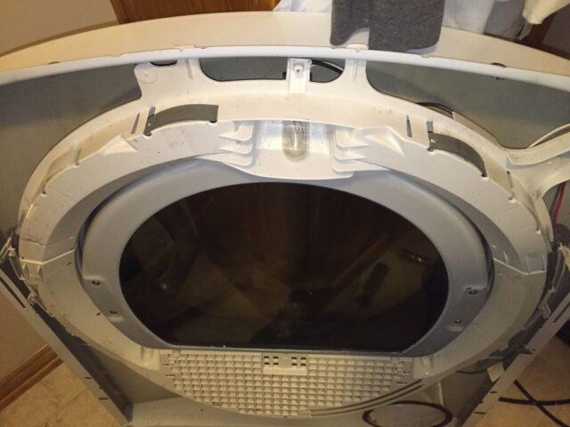
Mine where NOT OEM and they were all worn out:
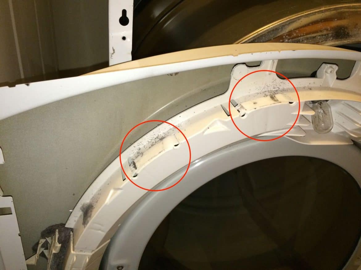
These two were completely worn out. As you can see from the picture below, the top glide and the bottom glide are both white. The top one, if it is a factory replacement, should be a dark-colored material. I had purchased third-party glides off of amazon and they turned out to be worthless and wore out in less than a month because they were made of a softer material. They were also loud too. Anyway, if you have the dryer torn apart you ought to replace these while you are in there if they are worn out:
If your drum glides are worn through make sure to replace them. I have the part numbers and all the steps to replace them (it’s easy) on my article here:
How to Fix Squeaking GE DCVH515EF0WW Dryer-Replace Drum Glides
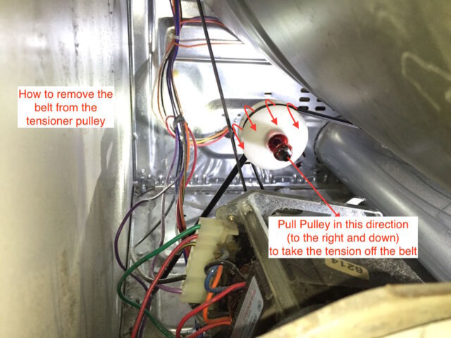
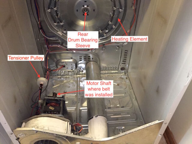
Step 11: Remove the belt from the idler pulley and motor shaft.
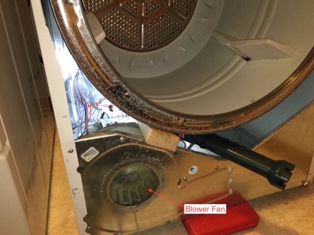
We need to remove the dryer drum so we can get at the bearing that is attached to the back of the drum so we need to disconnect the belt from the idler pulley so the drum will be freed from the dryer. You can see the idler pulley via the lower left corner, just above the blower fan:
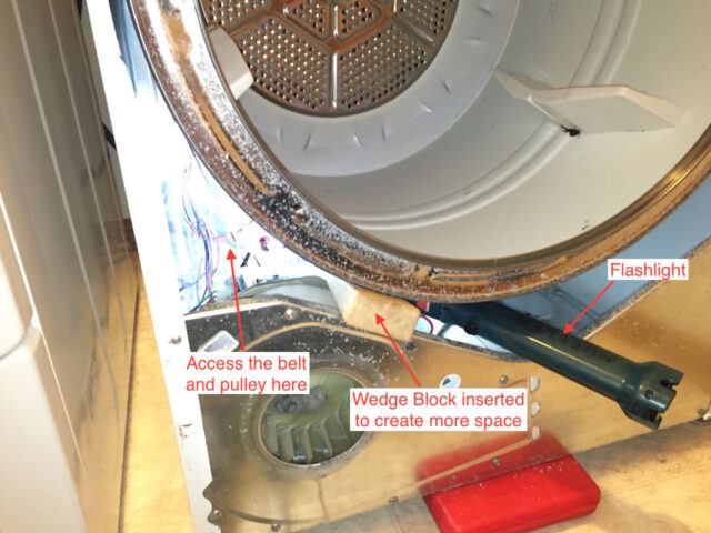
If you shine a flashlight back in there and look into that triangular-shaped access hold this is what you will see:
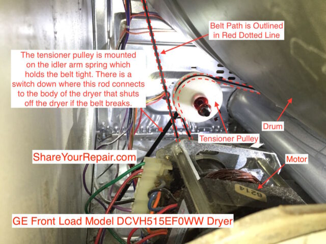
To remove the belt from the pulley push the pulley down to take tension off the belt and work the belt off as shown below:
Move the belt to the right side of the pulley and make sure it is not on the shaft of the motor:
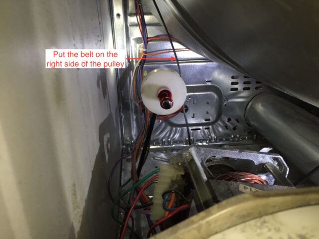
Also make sure the belt is not looped under the motor shaft which is out of sight in the picture below.
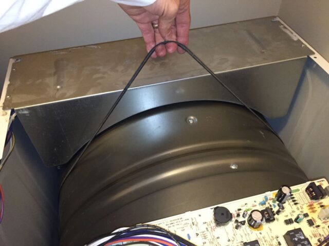
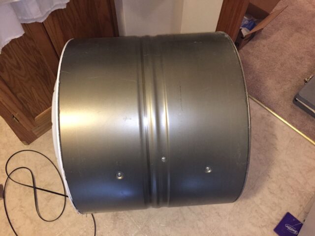
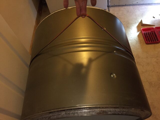
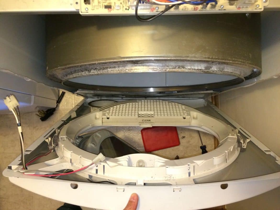
Step 12: Remove the drum.
Use the belt to lift the back-end of the dryer and grab the front lip with your fingers and slide the drum straight out towards the front. If you didn’t unhook the belt from the idler pulley AND motor shaft you will run into issues at this point. Here you can see me supporting the back-end of the drum:
Here’s the drum removed:
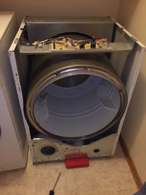
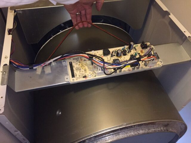
Here is the dryer with the drum removed:
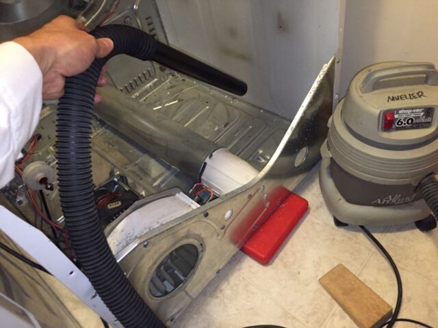
Step 13: Vacuum out your dryer.
While you have your vacuum torn apart you ought to vacuum out the inside of the dryer. There was some lint that had built up around the edges of our dryer:
Step 14: Disconnect the electrical connectors from the heating element assembly.
There are 9 connectors as shown below that will need to be disconnected. They are all similar type connectors and can be difficult to pull off. I used a pliers to grip the connector and carefully pulled them off. Do not pull by the wires! Also, I would recommend that you do not touch the heating elements. The oil from your skin can get on them and prematurely cause them to burn out and break.
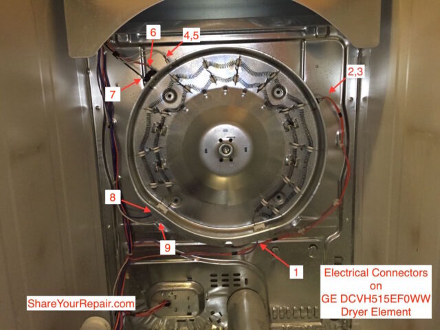
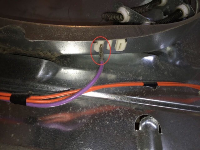
Close-up of #1, the lower right heating element connector with a single purple wire running to it:
Close-up of #’s 2 & 3 which go to the safety thermostat (thermal fuse), GE part number we4m137. Both of the wires are orange and it doesn’t matter which one connects to which terminal on the fuse:

Close up of #’s 4, 5, 6, and 7, which lead to the inlet control thermistor, GE Part we4m398 and the safety thermostat, GE Part we4m160
:
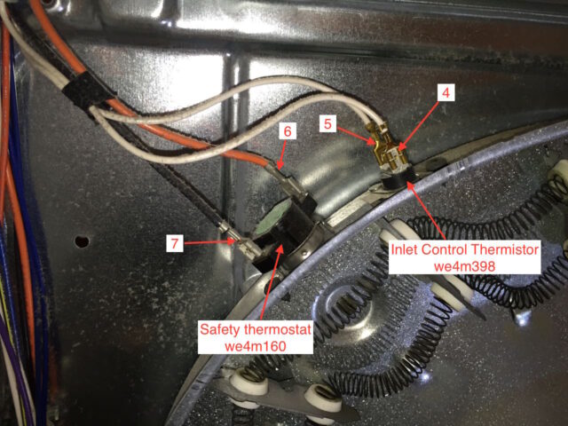
You will want to make sure the black wire goes on the left terminal and the orange wire goes on the right terminal of the safety thermostat. The two white wires don’t matter which one goes on which on the inlet control thermistor.
Close-up of #’s 8 and 9 which connect to the heating elements:
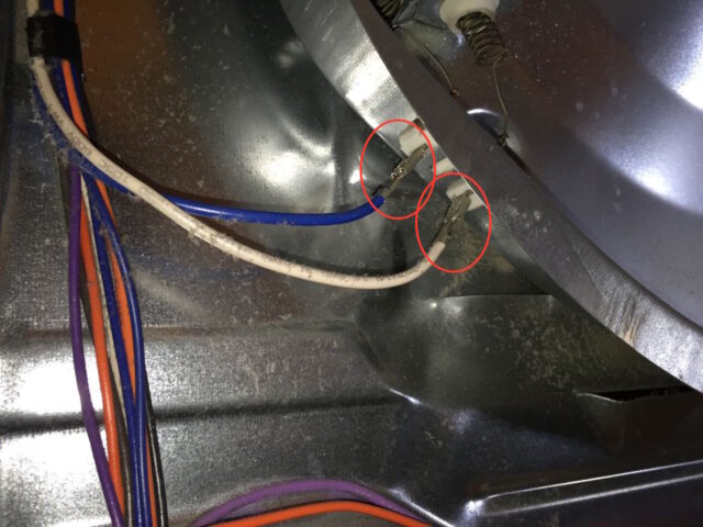
Note that the blue wire goes on the left one and the white on the right one.
Step 15: Remove the heating element assembly.
If you know you are replacing it go ahead and remove it. If you want to troubleshoot it in place you can. I was removing it for another reason so I will show the steps for removing it…
There are 4 Phillips head screws that hold the heating element assembly in place. For your info, the complete heating element assembly is GE part we11m23, and the elements only are GE Part number we11x10007
.

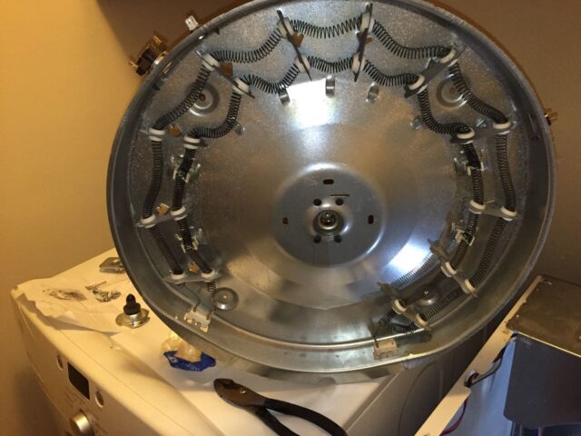
Here is the heating element assembly removed:
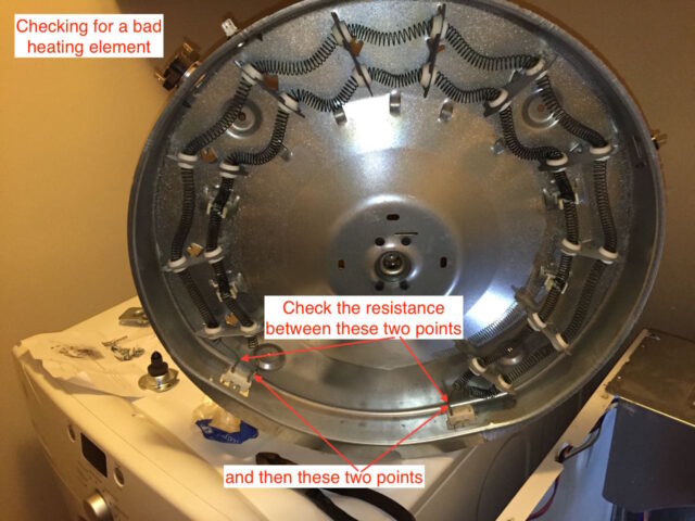
Step 16: Troubleshoot the heating element assembly.
With the heating element assembly removed you will be able to easily troubleshoot the element and all the components mounted on the assembly. To check for a bad element put your multimeter on the element between the following points and check to see if they are an open circuit (infinite ohms resistance):
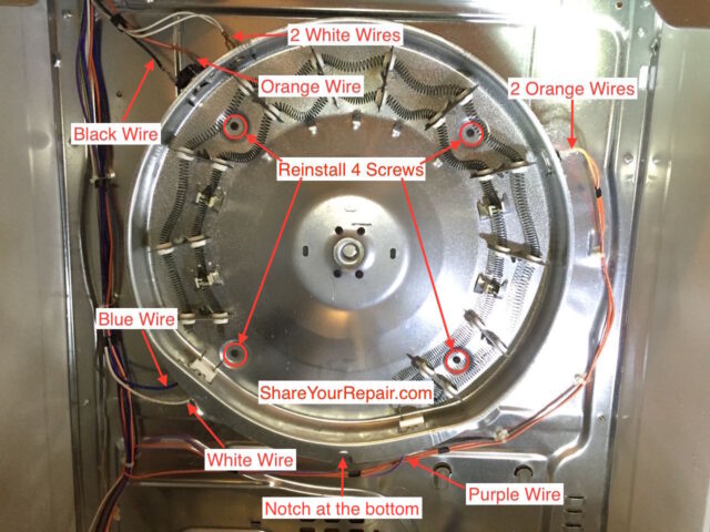
Step 18: Install the new heating element assembly.
Orient the heating element so that the notch is at the bottom as seen below, reinstall the 4 mounting screws, and connect the nine wiring connectors as shown below. If there are two identically colored wires, it doesn’t matter which one goes on which terminal (because it is like a fuse):
Step 19: Reinstall the belt on the drum.
If you wanted to change the belt now would be the time to get the new belt out. I went ahead and replaced the belt while I was doing all this and below is the old and new belt together. The new belt will be shorter since the old belt has stretched out:
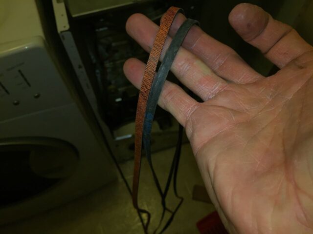
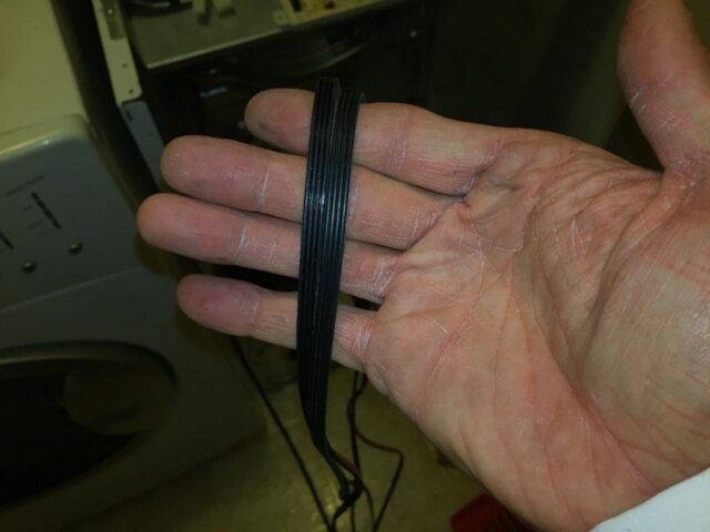
Make sure the ribbed side faces the drum (this is both belts side-by-side):
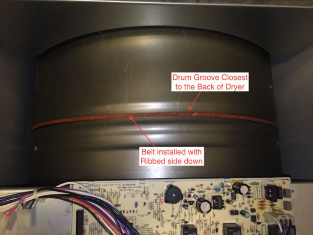
Slip the drum through the belt, ribbed side toward the drum, and align the belt on the groove closest to the back of the drum (you will be able to see wear on the drum to indicate the right place):
Step 20: Reinstall the drum into the dryer.
Supporting the back-end of the drum with the belt, slide the drum into the dryer body. You will need to pry out the sides of the dryer to get the drum to fit between them.
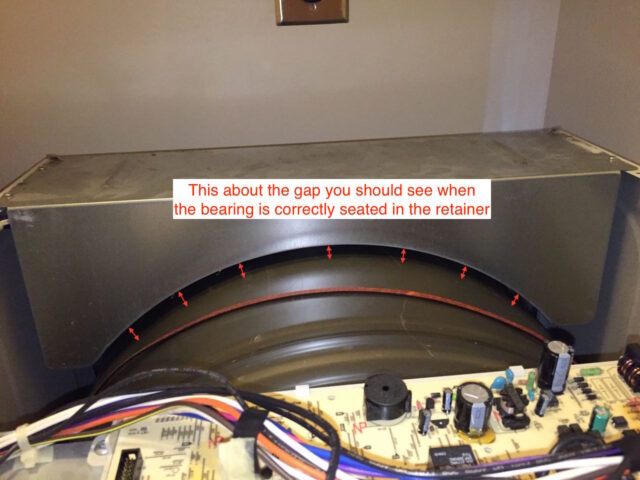
It takes some patience to align the drum up with the retainer bearing so the bearing fits in its place. Be careful to not “stab” the dryer elements with the bearings as you could damage them. You will know that you have inserted the bearing into the retainer when the top of the drum has the gap shown below:
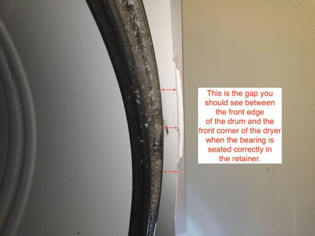
The front edge gap should look like this:
Step 21: Reinstall the belt on the motor and idler pulley.
First make sure the belt is correctly aligned and oriented on the drum. The belt should go in the groove that is closest to the back of the dryer and the ribbed side of the belt should face the drum as seen below:
Here’s how I set it up to access the belt and reinstall it on the motor and pulley:
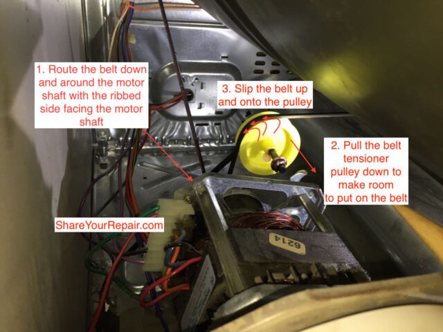
The belt is going to feel like it is too short, but it will fit. First put the belt on the motor shaft, second, bend the pulley down, and third, slide the belt up and over the lip on the edge of the pulley:
Step 22: Test the belt installation.
If the belt is installed correctly, when you turn the drum (while supporting the front edge of the drum), the blower will turn, since it is directly connected to the shaft on the motor:
Step 23: Reinstall the front panel on the dryer.
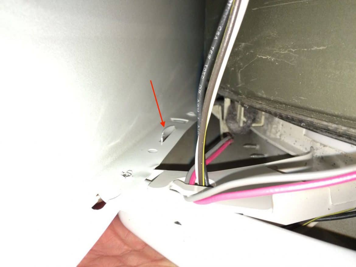
You will need to slip the two bottom “slots” on to the two screws you loosened in Step 7.
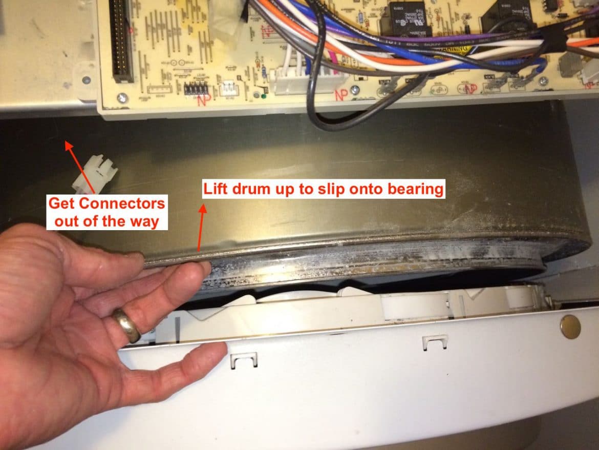
As you lean the top of the front panel towards the dryer you will need to move the wiring connectors out of the way so they don’t go into the drum and also you will need to lift the drum up so it slips on to the bearing assembly:
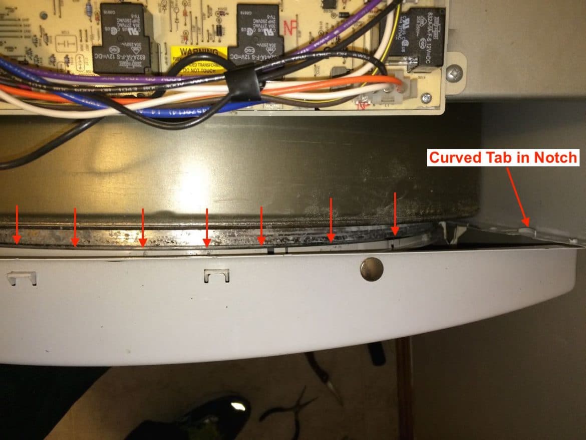
You will also need to line up the curved tab on each edge of the front panel with the notch on the sides of the dryer. I needed to squeeze the sides of the dryer in to line it up (both sides are the same):
Here’s a picture of the front panel in place:
Reinstall the upper front panel screws:
Tighten the two lower front panel screws:
Step 24: Reconnect the light and door light switch electrical connectors.
These connectors only have one way they can go on and one has 3 wires and the other has 2 so you can’t get them mixed up:
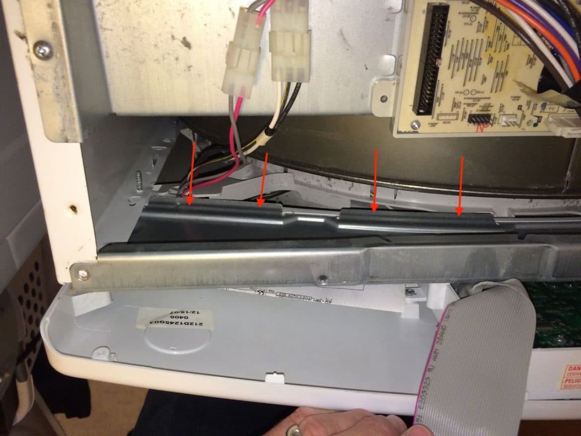
Step 25: Reinstall the control panel.
The control panel has a slot on the bottom edge that sits down over the metal lip on the dryer body as illustrated below:
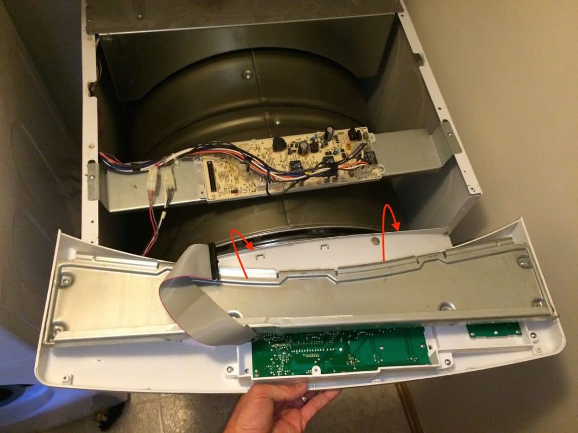
Here the control panel is set back on to the body (arrows indicate where the control panel fits over the edge of the metal frame):
Reconnect the control panel ribbon cable. The female side (on the dryer) has a notch that fits a piece that sticks out on the connector so it will only fit one way:
Reinstall the two screws into the left and right ends of the control panel:
Step 26: Reinstall the dryer top panel.
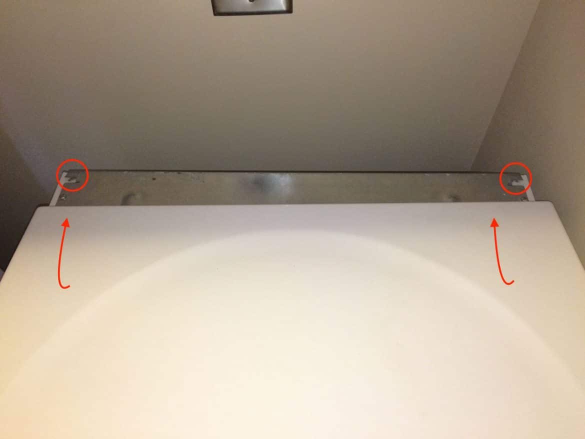
There are two “catches” that hook into the underneath side of the top metal panel (circled below). Set the back edge of the top panel on the top of the dryer and slide it back, centering it on the top of the dryer, and once it locks in place you can set down the top.
Then reinstall the two long top panel screws:
Step 27: Reinstall the back molding.
Slide the back of the bezel in place and reinstall the three Phillips head screws:
Step 28: Cautionary Note
If you have perchance pulled your dryer away from the wall you may want to verify that the dryer is still correctly connected to the exhaust pipe on the back. It isn’t dangerous to have it disconnected but you will vent dryer lint all over your house if you blow the exhaust into your laundry room.
Step 29: Plug it back in
If your heating element was bad your dryer should heat up right away. Now you’ve fixed your dryer heating element issues and saved a lot of money.
Other Links:
Amazon Associate Disclosure: As an Amazon Associate I earn from qualifying purchases. This means if you click on an affiliate link and purchase the item, I will receive an affiliate commission. The price of the item is the same whether it is an affiliate link or not. Regardless, I only recommend products or services I believe will add value to Share Your Repair readers. By using the affiliate links, you are helping support Share Your Repair, and I genuinely appreciate your support.