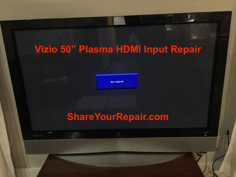
If you have a 50″ Vizio Plasma TV that has a bad HDMI input (i.e. you get a “No Signal” message when you change to that input), you can get it back up and working again for not that much money. Our 50″ Plasma TV was in perfect shape except only one of the two HDMI inputs worked. After trying different HDMI cables and different input devices, I determined that the HDMI jacks or something on the HDMI channels had failed. After some searching online I discovered you can buy the entire circuit board for these TV’s, which includes the HDMI jacks, so I wanted to give it a shot and make our old TV like new again. Read along so you can see how easy you can make your big screen like new for under $50!!
Vizio 50-Inch Plasma HDMI Repair
Hardware:
- Vizio P50HDTV10A 50″ Plasma TV
Tools Needed:
Parts Needed for HDMI Port Repair:
Other Vizio 50 Plasma Boards:
I went ahead and identified replacement board for ALL the internal boards, just in case you need them:
- Vizio, Hp, Lg 6871QDH089A Buffer Board 6870QDC005A (not available on Amazon anymore)
- Vizio P50HDTV10A Power Supply Board 6871QIH001A (not available on Amazon anymore)
- Vizio P50HDTV10A 6870QZC104C 50X3 6871QZH044C ZSUS Board 5569 (not available on Amazon anymore)
- Vizio P50HDTV10A XR XL Buffers 6870QSC008A 6870QMC007A
- Vizio P50HDTV10A Tuner Board 3850-0012-0187(5A)
- Vizio P50HDTV10A Control Board 6870QCC013A 6871QCH059B
- Vizio 6871QYH039A Y Sustain Board
Background
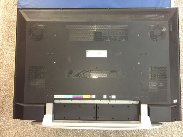
Despite swapping out HDMI cables, trying different input devices, I still couldn’t get the HDMI 2 port on our 50-inch to work. Even if your HDMI 1 port wasn’t working, this repair would work for you too as this fixes either port. Anyway, the HDMI ports are pictured below:

Repair Instructions:
Step 1: Unplug the TV.
Please make sure to unplug the TV before working on it as you could electrocute yourself.
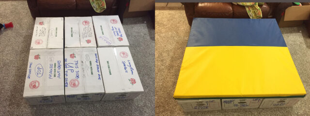
Step 2: Prepare a safe place to lay the TV face down.
You are going to want to lay the TV face down but you do not want to scratch the screen. If your TV doesn’t have a base installed, then clean carpet should be fine. For me, the problem is that I needed to be able to lay the screen flat and allow the base to stick out on the end. We had just moved so we had a bunch of cardboard boxes laying around so I simply made a platform of boxes and then covered them with a tumbling mat, to serve as the soft surface to lay the TV:
Step 3: Carefully lay the TV face down.
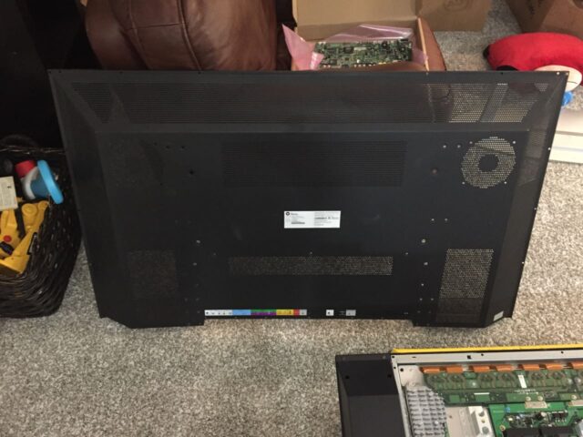
You should get a second person to help you with lifting this TV as it weighs 122 lbs with the base/stand installed (108 without the base). Lay the TV face down as seen below, with the weight of the TV evenly distributed on a soft, flat surface, with the stand sticking out the end so you can remove it:
Step 4: Remove the stand.
There are 12 Phillips-head screws that hold the base on, remove them and keep track of them.
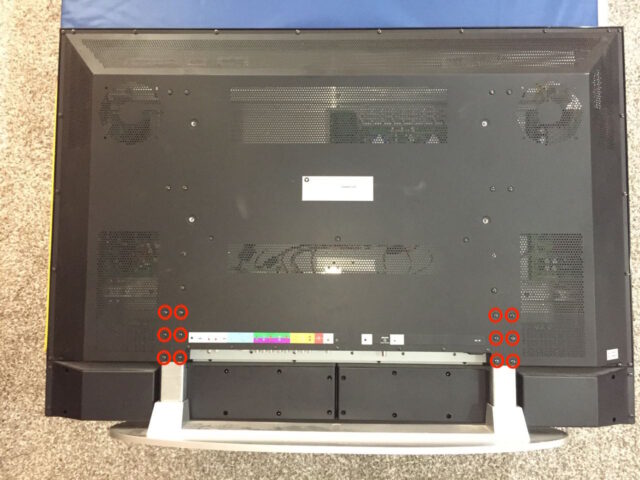
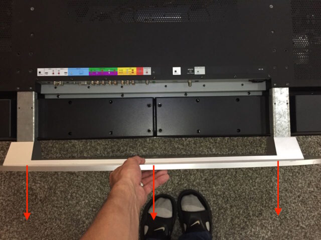
There are two different sized screws involved in the removal of the exterior case. I’ve created a diagram below to help you keep track of them. Once you have the 6 case screws removed you can pull the stand straight down and out of the TV:
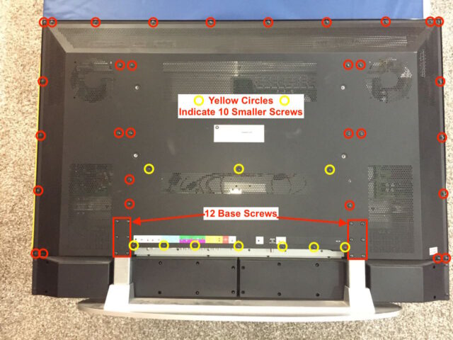
Step 5: Remove the back case screws.
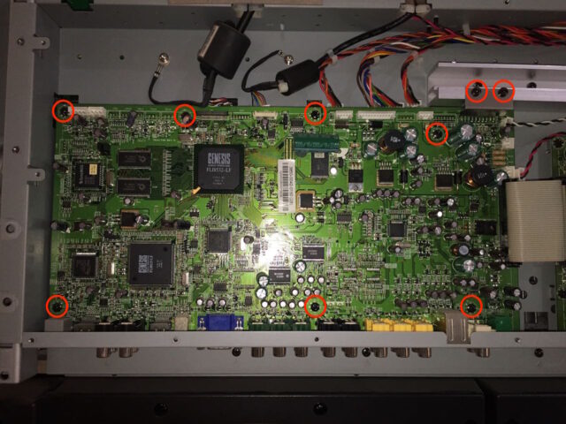
Below is a diagram of the 41 screws you need to remove. There are two different sizes of screws on the back. The 10 yellow circles indicate the smaller screws and the 31 red circles are a larger (same) size. I’m not counting the 12 base screws you already removed.
Step 5: Remove the back case (cover).
Carefully lift off the back cover. Caution: it may have sharp edges. I was able to get it started by lifting the lower edge as seen below. Don’t lift it all the way up as it sits down in a channel along the sides. Get it started as seen below and then grab it along the outer edges and lift it straight off and set aside.
Set it aside in a safe place where you won’t bend it:
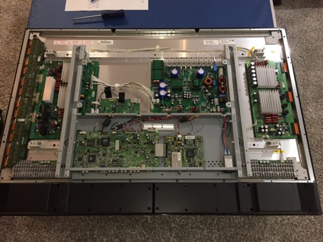
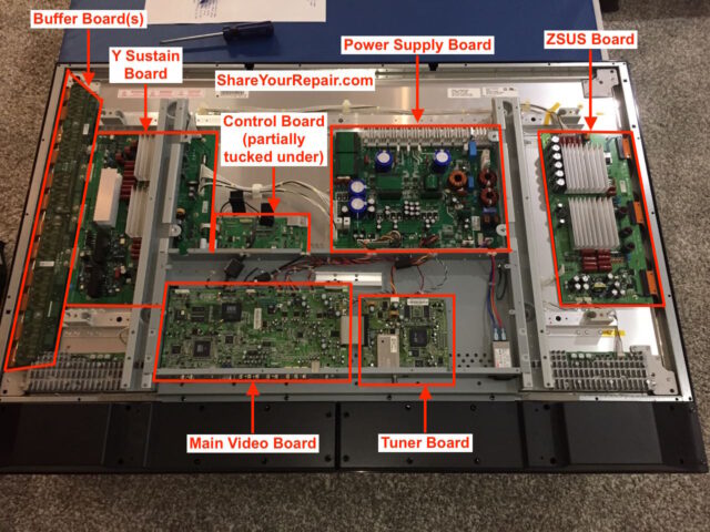
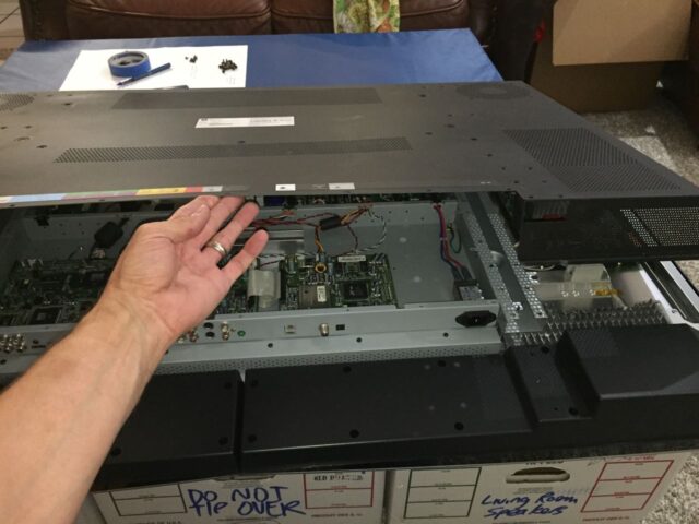
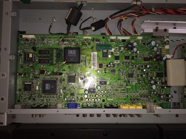
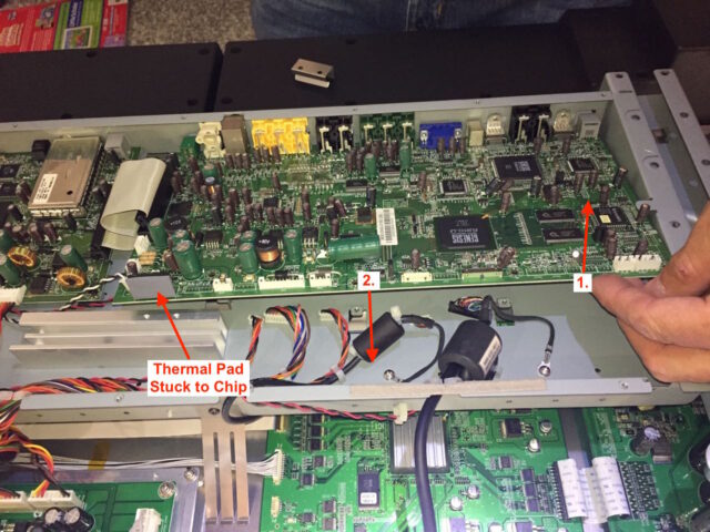
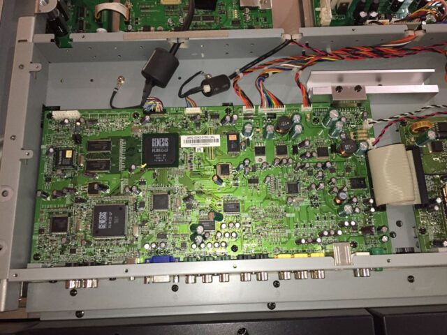
Step 6: Locate the main board.
The main board is the circuit board that is connected to all the audio/visual connectors, on the bottom (middle) left of the picture below. I did some sleuthing and have identified pretty much all the components of this television:
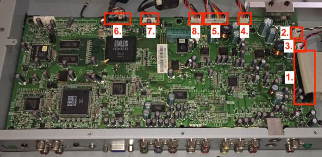
Step 7: Disconnect the eight electrical connectors from the main video board.
Caution: Be careful to not discharge static electricity onto the inside of the tv as you could cause yourself bigger problems. Periodically touch the grey metal case to discharge yourself.
Carefully disconnect the eight electrical connectors from the board. Some of these connectors pull straight up and off the board, some pull up and parallel with the board. Be careful, take your time, and make sure you don’t damage a wiring harness and cause yourself bigger problems. Here are the connectors in the order I removed them and I’ll use these numbers to refer to them below as I describe how they are removed:
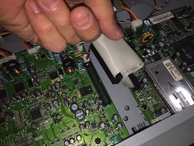
Step 7a: Electrical Connector #1: Parallel Ribbon Cable
This cable is exactly like the old-fashioned EIDE parallel hard drive cables you are used to disconnecting. There is nothing to grab, except the ribbon, so carefully wiggle it around and pull it straight out from the board:
Step 7b: Electrical Connector #2: 2-Wire White Connector (Black, White Wires)
This connector pulls straight up and out. Get your nails under the very top edge of the connector and pull up.
Step 7c: Electrical Connector #3: 2-Wire White Connector (Red, Black Wires)
This one pulls straight out exactly like connector #2:
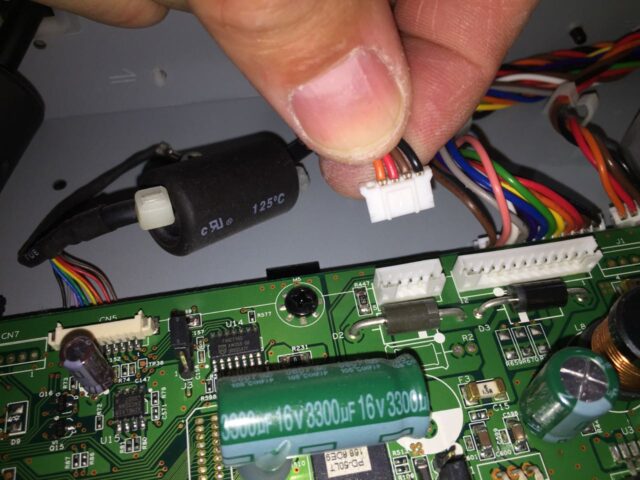
Step 7d: Electrical Connector #4: 4-Wire White Connector (Orange, Red, Brown, Black Wires)
Pull straight up, away from circuit board, the same as the previous three connectors:
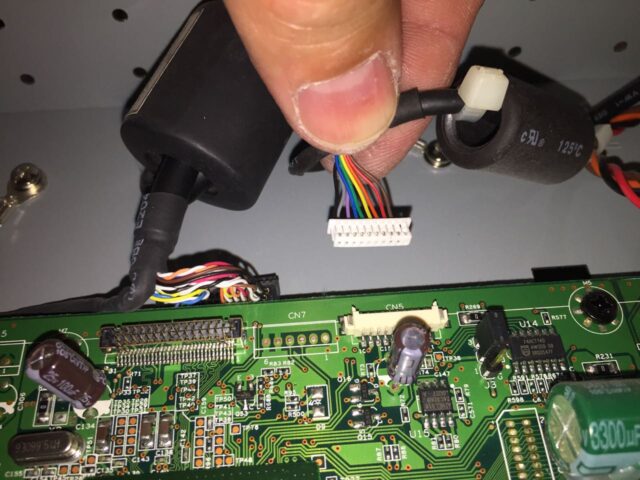
Step 7e: Electrical Connector #5: 12-Wire White Connector (Brown, Pink, White, Grey, Purple, Blue, Green, Yellow, Orange, Red, Brown, Black)
Pull straight up, away from circuit board:
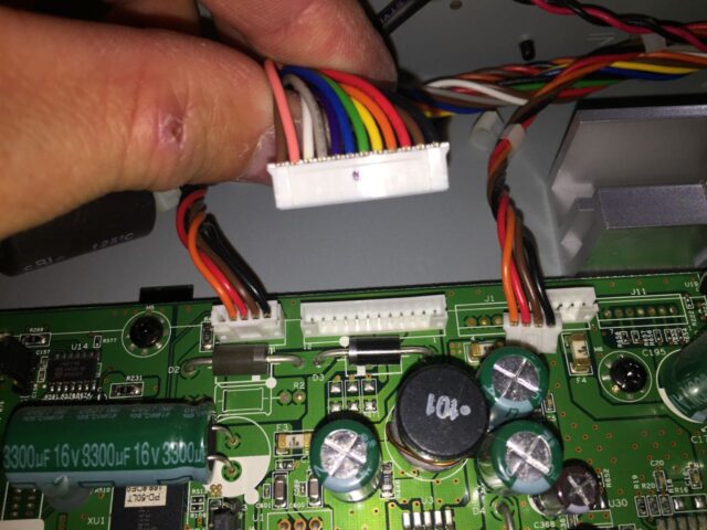
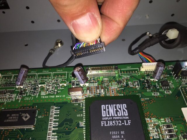
Step 7f: Electrical Connector #6: 22-Wire Black Connector (LOTS of different colors of wires)
Pull this straight up, away from the circuit board:
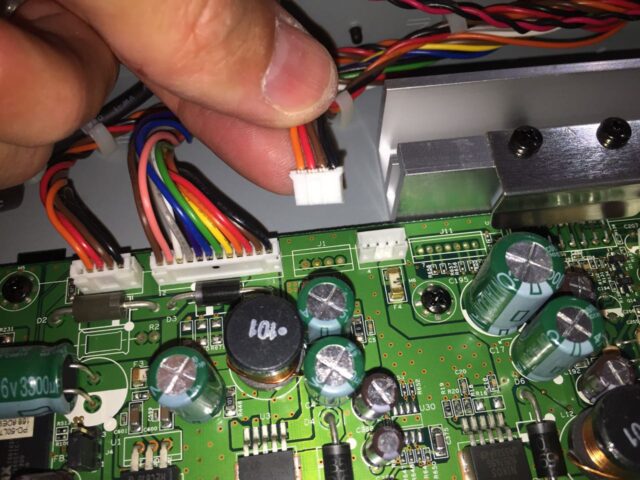
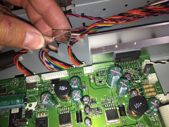
Step 7g: Electrical Connector #7: 9-Wire White Connector (Black, Grey, Purple, Blue, Green, Yellow, Orange, Red, Brown Wires)
This connector is different from the preceding ones in that it disconnects parallel with the surface of the circuit board. Catch your finger nail on the end/edge of the connector and gently get one end started and then to the same to the other end and then pull straight out, parallel with the circuit board:
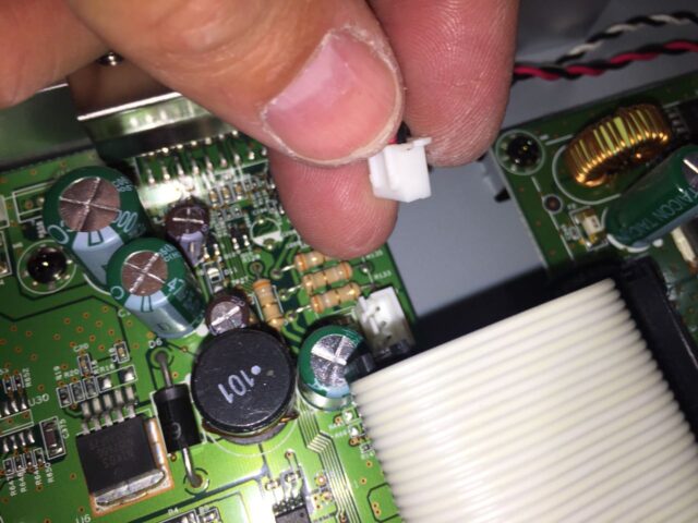
Step 7h: Electrical Connector #8: 4-Wire White Connector (one wire INTENTIONALLY missing in this connector)
This connector pulls straight up and out of the board (perpendicular to the top of the board):
Here is what you’ll have when they are all disconnected:
Step 8: Remove the 9 Top Screws from the Video Board.
Remove the 9 Phillips-head screws from the top of the board as indicated below. The top right two screws are being removed from the heat sink spring clamp.
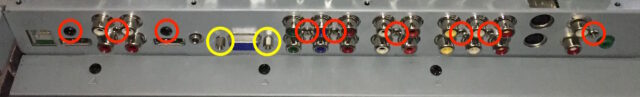
Step 9: Remove the 9 screws and 2 VGA adapter studs from the connector side of the circuit board.
The Phillips-head screws are circled in red and the two 5-mm hex-head studs are circled in yellow below:
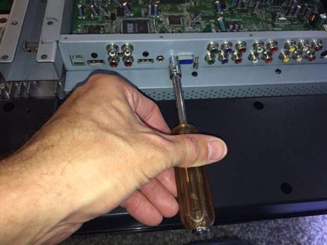
I used a driver handle and a 5-mm socket tip to remove the VGA adapter studs:
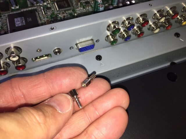
Here they are removed:
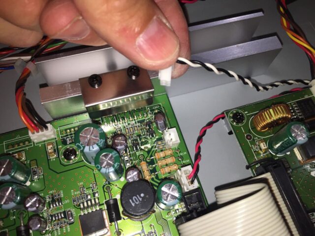
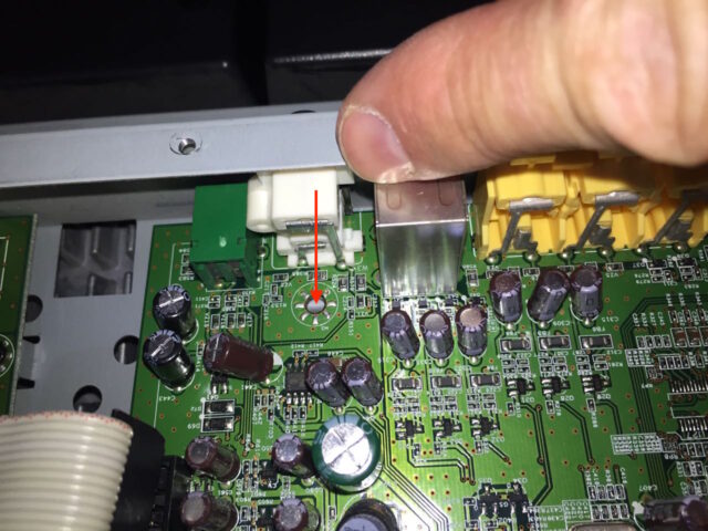
Step 10: Remove the heat sink clamp.
One of the semiconductor chips is attached to an aluminum heat sink. Below is a close-up of the clamp. It simply squeezes the chip to the heat sink and the screws hold it down on the chip and heat sink:
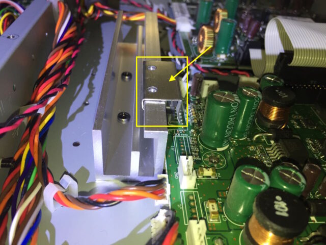
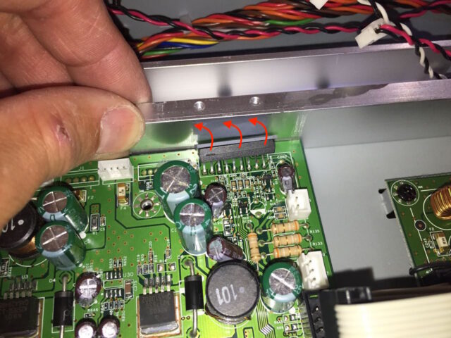
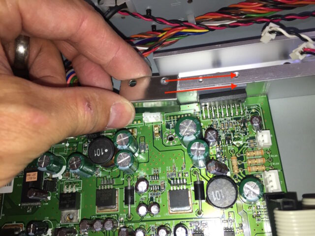
To remove it, simply slide it to the side as directed below:

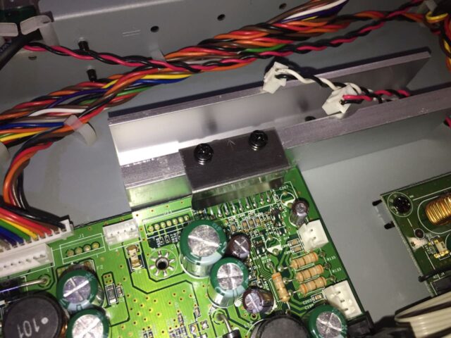
Here you can see the clamp removed
Step 11: Remove the board from the TV.
Carefully lift the board up from the edge, starting on the edge opposite the connectors. Once you have lifted up that edge, pull the board away from the connector end (towards you in the picture below), pulling the connectors out of their holes in the TV case.
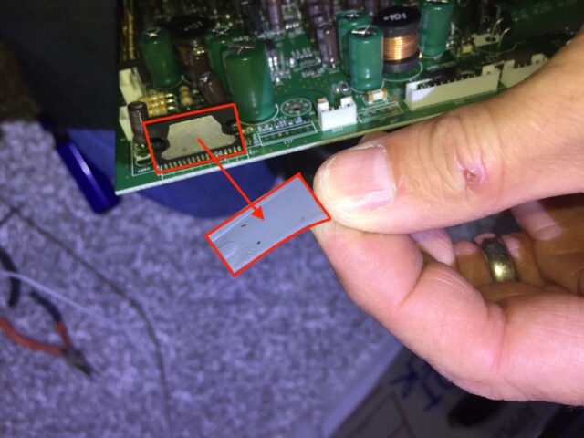
Note: There is a silicon thermal conducting pad in-between the heat sink and the chip you removed the heat sink spring clamp from. You’ll want to keep track of that when you remove the board–it may stick to the heat sink, it may stick to the chip, or it may fall off. Here I am peeling off the thermal pad:
Step 12: Install the new board into the TV.
Step 12a: Install the silicon thermal pad.
First “stick” the silicon thermal pad to the same chip on the new board that you took it off of–it should be centered on the chip. It should stay pretty well in place on its own.
Step 12b: Insert the board into place.
Insert the connector-end of the board first and then set the opposite edge of the board down into the TV. Don’t worry about the chip with the thermal pad lining up perfectly at this point–we’ll get to that in a bit.
Align the holes in the board to the threaded holes in the TV case:
Step 12c: Install the heat sink clamp.
Carefully bend the chip up on the heat sink:
The chip is not going to stay in place but that is ok, bend it as much as you can and that’s fine. Then, while holding the chip up against the heat sink, slide the heat sink clamp into place from the side:
Step 13: Reinstall the video board screws.
Carefully reinstall the following 9 Phillips-head screws, being careful not to damage the circuit board:
Here’s a close up of the reinstalled heat sink clamp:
Reinstall the 9 connector face screws and the two VGA lugs:
Here’s the new board installed:
Step 14: Lay the back cover back into place.
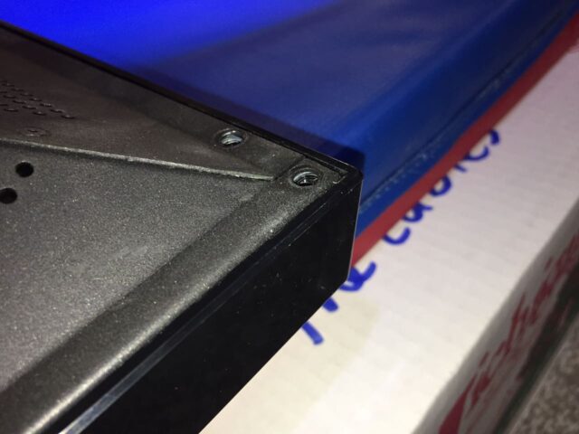
Carefully place the back cover on the TV. Make sure the corners set down into place.
The top corners should set down into the channel as seen below:
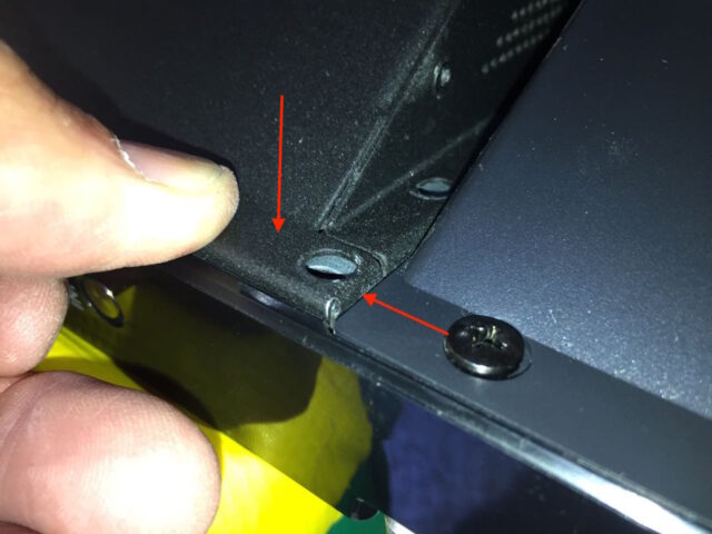
Te bottom corners should be nearly flush:
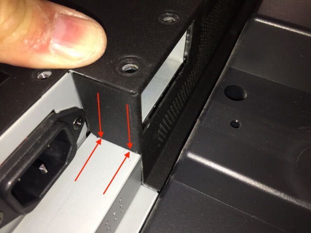
Around the opening for the stand legs the black back should be flush with the silver exposed metal as seen below:
Step 15: Reinstall the back case screws.
Paying attention to keep the shorter (yellow) circle screws in only the middle holes, reinstall the screws in the locations indicated below. If you are installing the stand, go ahead and insert the legs and line up the holes before installing the stand screws, otherwise you can install the screws into the stand holes even without the stand installed.
Step 16: Test out that broken HDMI port.
As soon as I could, I tested out the HDMI 2 port, with my Apple TV. And it works!!!
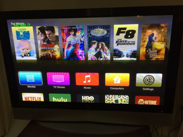
For under $50 I made this TV like new again and fully functional!!
Other Resources
- Vizio 50-Inch Plasma P50HDTV10A User Manual (pdf)
- Vizio, Hp, Lg 6871QDH089A Buffer Board 6870QDC005A
- Vizio P50HDTV10A Power Supply Board 6871QIH001A
- Vizio P50HDTV10A 6870QZC104C 50X3 6871QZH044C ZSUS Board 5569
- Vizio P50HDTV10A XR XL Buffers 6870QSC008A 6870QMC007A
- Vizio P50HDTV10A Tuner Board 3850-0012-0187(5A)
- Vizio P50HDTV10A Control Board 6870QCC013A 6871QCH059B
- Vizio 6871QYH039A Y Sustain Board
- Original Vizio VUR4 LCD TV Remote Control
Amazon Associate Disclosure: As an Amazon Associate I earn from qualifying purchases. This means if you click on an affiliate link and purchase the item, I will receive an affiliate commission. The price of the item is the same whether it is an affiliate link or not. Regardless, I only recommend products or services I believe will add value to Share Your Repair readers. By using the affiliate links, you are helping support Share Your Repair, and I genuinely appreciate your support.
Hello John, great post. Thanks tons, I might have to do this. Do you think it’s possible to detach the HDMI ports from the main board and replace them? Just some soldering, I would think, unless it’s just not very possible.
Tim, it is certainly possible but I would not recommend it unless you do a lot of soldering/unsoldering like this. First of all we don’t know for sure that it is the connector that is bad. I would assume it, but we don’t know for certain. You will need to do most of the work of disassembling the TV and pulling that board out so you can get at both sides of the board, so it wouldn’t save any work in that manner. Then you must not damage anything near the connector when you are heating up the board. Often it is difficult to transfer enough heat to the board to heat up all the parts to pull out a large connector like that, which is risky. So that’s my opinion. Let us know what you do and how it goes.