Hardware:
- Door Chime AC transformer (example) (ours reads 18.4 VAC but they can be adjusted to a range of voltages via a set screw on the transformer)
- Electric Door Strike/Latch
- Push button doorbell button (example of a lighted or unlighted.)
- Wired Door Chime (example)
- Push-button door-bell switches (surface-mount type for inside and for recessed round for outside)

I live in Chicago and have an iron fence at the public sidewalk with a locked gate. We don’t want to have to walk all the way out to the sidewalk every time we need to let someone in so we have a doorbell at the gate and have an electric latch where we can push a button at our front door and “buzz” people in. Here I’ll explain how to wire it all up.
First, you are going to need a power source. If you have a wired doorbell you probably already have one, an AC transformer. For most homes it is located in the furnace room. It will look very similar to this:
 |
| Low voltage AC door chime transformer |
Hopefully your transformer isn’t wired to the conduit using the wiring from the old thermal couple you changed on the water heater but mine was hanging from its wires so I wanted to relieve some of the pressure so I used what was on hand at the moment 🙂 Usually they have one tab on the side that the electrician who installed it screws to one of the junction boxes.
This the transformer is what powers your doorbell when someone pushes the button. We are going to use it to power the electric door latch as well. In this situation, the guy who wired this one up used CAT-5 cable and used 4-5 of the conductors joined together for each of the two connections. That works. In my last install of this I used some audio/visual wiring cable that I picked up somewhere for free. I’m not going to go into detail on what kind of wiring you should use. You can go to Home Depot and tell them what you want to do and they can suggest some good wiring. You’ll need a minimum of 3 conductors for the run that goes out to your gate (so you don’t have to run two wires).
I’m going to describe the wiring as shown in the diagram below. The central point of the schematic (in the center and bottom of the picture) is located with the low-voltage transformer. All the wires will run to this point.
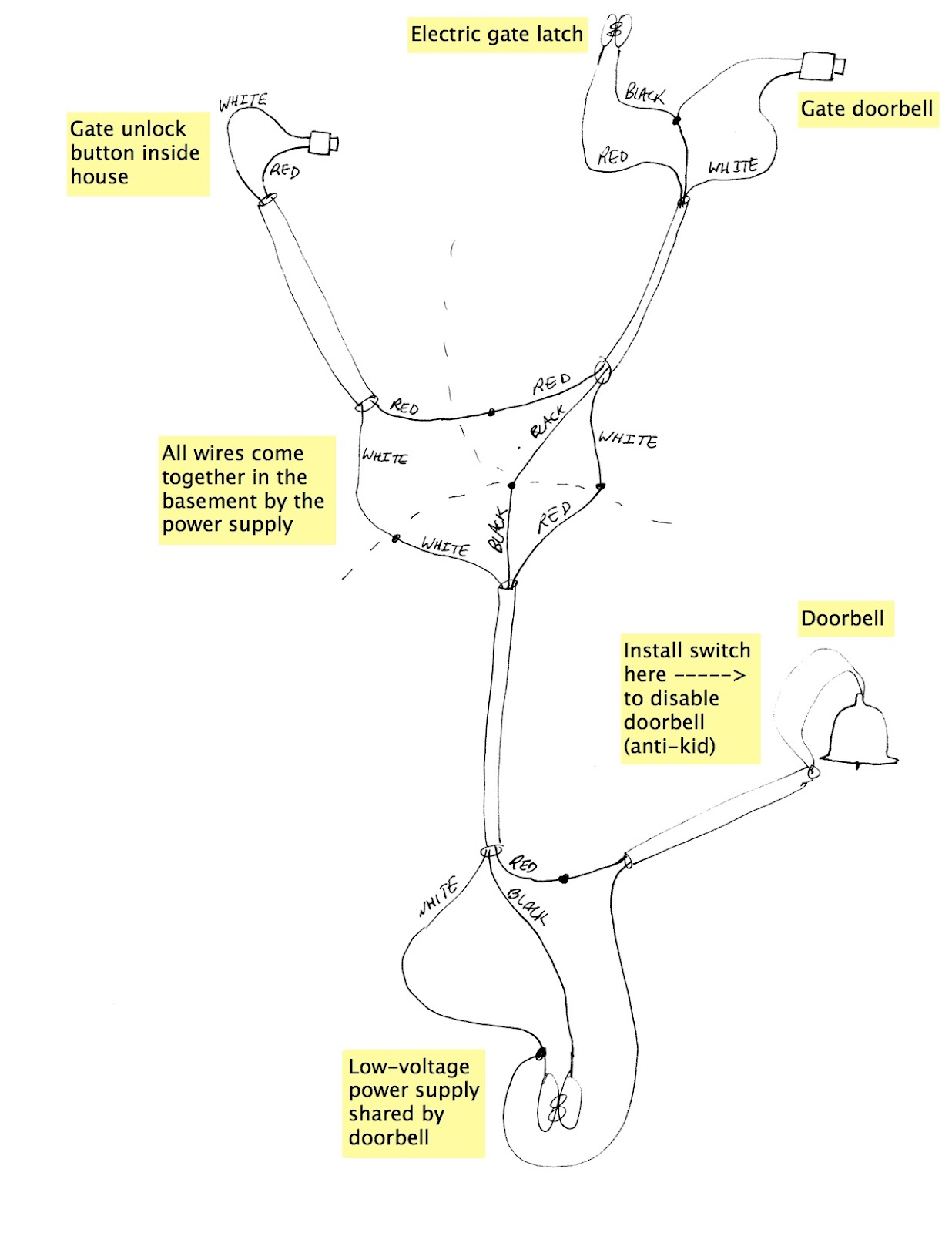 |
| Wiring schematic for electric gate latch and doorbell |
Step 1: Pick a place for the button that will activate the gate latch and run the wiring. You need to pick a place to put the indoor push-button doorbell button that will activate the electric latch at the gate. Only you can determine this location but you’ll need to be able to run one pair of wires to it from the transformer. I’d also put heavy weight towards putting it close to the window where you can see the front gate or by the intercom where the person will be calling up to request the gate/door opened. Note: the colors don’t mean anything in the diagram above. I just picked a color that was available in the cable I used and then when I was at either end of the cable I knew which wire needed to connect to what. I strongly recommend printing off the picture above and using it as a guide, adjusting the color labels with the colors you chose–it will make it much easier when you are connecting everything together at the transformer location. Run your wiring from the transformer location to the doorbell and pick one pare of wires to connect to it and note their colors on the diagram above (write in your own colors). Write the corresponding colors in place of my color names on the other end of the run of wiring (for example if your wires connected to the doorbell switch are green and yellow then you’ll need to cross out my white and red and write green and yellow for them on both ends of the cable. This wiring run is just a loop and the gate latch button connects the circuit of the loop.
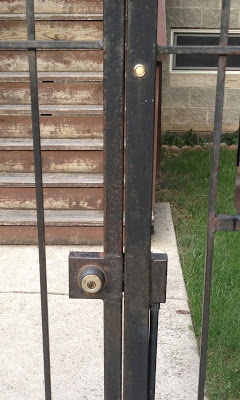
Step 2: Run the wiring out to your gate. BTW: One prerequisite is that your gate is physically configured for an electric latch. There must be a box for mounting the electric latch in for this setup to work. Also, I’m not going to be able to cover most of the details of getting the wiring out to your gate–you’ll have to figure that out to fit your situation. In my last application I ran the wire from the furnace room through the wall of the building right under the gas line that penetrated the building (that way I didn’t have to make a new penetration). I then dug a trench with a spade along the side of the house, under the porch, along the edge of the sidewalk, on out to the gate. I ran a piece of conduit up to the box that was welded for the electrical latch on the gate. Drilling a hole in this box was pretty tough because I only had a 1/2″ drill. You’ll have to figure out how you want to do that. You could tap into the bottom of the post and go up the post too. This is how it looks at my house:

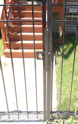
The one I installed at my neighbor’s house. I can’t remember why I put the doorbell button so low:

In the box at the gate you will pick one wire that will run to both the electric latch and one terminal of the push button doorbell button. It doesn’t matter which of the electric latch wires you hook it up to (because it’s AC power) and they probably are both the same color. You’ll need to note the colors so you can keep track of things according to my schematic above. I drilled a hole higher on the post for the doorbell not to be so low and just ran a set of wires to connect to the cable running from the house.
Step 3: Run the wiring to your doorbell. This step very likely is already done for you if you already have a doorbell in your place. If you have to disconnect your old doorbell switch then you’ll have to figure out how to merge your pre-existing wiring with this schematic. If not, you’ll need to pick a place to mount your doorbell and run one pair of wires to it from the location of the transformer. On the doorbell end, both wires will be connected to the doorbell and on the transformer end, one will be connected to one side of the transformer as shown in the diagram and the other goes off to the doorbell button at the gate.
Step 4: Connect all the cables at the transformer location. Finally use all your notes you took on the schematic when you were picking colors and connecting the doorbell, electric latch button, doorbell button, and electric latch. The better your notes the easier it will to know for sure it will work when you are done.Other Options:
- Doorbell On/Off Switch
We have people prank ring our doorbell quite often so I installed a switch to shut off the doorbell when the kids are napping. On the schematic above you can see the location where you can put the switch. An example of the pull-string kind we used is here. Simply cut the wire that runs from the gate doorbell button to the doorbell chime and insert the switch. This will cut the power from the doorbell if someone is to ring it BUT does not cut the power from the electric latch if you want to open it for someone. We just drilled a hole in the bottom of the plastic cover of the doorbell like shown below. The only trick is remembering if it is on or not for when the UPS guy is supposed to come. That solution will have to be left another blog entry.
 |
| Door chime on/off switch |
Amazon Associate Disclosure: As an Amazon Associate I earn from qualifying purchases. This means if you click on an affiliate link and purchase the item, I will receive an affiliate commission. The price of the item is the same whether it is an affiliate link or not. Regardless, I only recommend products or services I believe will add value to Share Your Repair readers. By using the affiliate links, you are helping support Share Your Repair, and I genuinely appreciate your support.

I have a video door answering with gate latch unlock ( no buzzer at gate ) . I perched a small 12v buzzer and wired to the strike on the gate . The strike will work (kinda) and the buzzer nothing , so I am not doing something proper.
Can you help ? The buzer works great at the power box so it is good.
Gene, thank you for the question. It’s not possible for me to troubleshoot your situation from afar without a schematic or getting my hands on it. If you can describe how you have it connected I can attempt to help you but with what you’ve shared, I can’t be of much help. Sorry. -John